
Arduino Optical Water Level Sensor: 배선 & Code Guide
An arduino optical water level sensor hookup is simple for a DIY tank project: connect sensor VCC to Arduino 5V, sensor GND to Arduino GND, and the sensor digital OUT wire to a GPIO pin such as D2. Your sketch reads that GPIO as HIGH or LOW, then uses the result to switch an indicator LED, 버저, 릴레이 모듈, or pump control circuit.
This guide focuses on the practical wiring, sketch structure, relay safety, debounce handling, and the point where a breadboard prototype should become a production-ready sensor design. For optical sensing basics, use our full 광학 레벨 센서 explainer instead of repeating all theory here.
Basic Arduino Hookup: 5V, GND, OUT to GPIO
Most 5V optical infrared water level sensor modules used with Arduino have three signal-side connections:
- VCC / + → Arduino 5V
- GND / - → Arduino GND
- 나가세요 / 의 / 신호 → Arduino digital input pin, 예를 들어, D2
After wiring, open the Arduino Serial Monitor and print the pin state. Test the sensor tip in air, then touch it with water. One state will read HIGH and the other will read LOW. Do not assume every module behaves the same way. Some boards output HIGH when dry and LOW when wet; others are inverted depending on the circuit, 트랜지스터 출력, or pull-up design.
For a visual reference, see our dedicated 배선도 가이드.
Components and Pinout Table
| 항목 / Pin | 연결됨 | 목적 | 노트 |
|---|---|---|---|
| Arduino Uno, Nano, or compatible board | USB / 5V supply | Reads the sensor and controls output logic | Start testing from USB before adding a pump |
| 5V optical IR water level sensor module | 5V, GND, GPIO | Detects wet/dry state at one liquid level point | A 5V IR 센서 모듈 is easiest for Arduino prototypes |
| 센서 VCC | Arduino 5V | Powers the sensor module | Confirm the module supports 5V before connecting |
| 센서 GND | Arduino GND | Common reference | Required for stable readings |
| 센서 꺼짐 / 의 | Arduino D2 or another GPIO | Sends HIGH/LOW signal | 쓰다 INPUT 또는 INPUT_PULLUP based on module output |
| Relay module IN | Arduino output pin, such as D8 | Controls pump switching | 릴레이 모듈을 사용하세요, not a bare relay coil directly from Arduino |
| Relay module VCC/GND | 5V relay supply / 그라운드 | Powers relay electronics | Some relay boards need more current than Arduino can safely provide |
| Pump | Relay contact side + pump supply | Moves water | Pump supply must match pump voltage and current |
| Optional LED / 버저 | Arduino output pin | Safe first test load | Test logic before connecting pump |
How the Optical Sensor Behaves in a Real Water Project
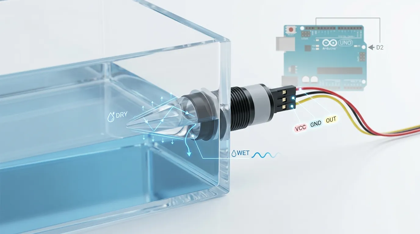
An optical water level sensor normally uses an IR LED, phototransistor or photodiode, and a molded prism tip. 프리즘이 마른 상태일 때, infrared light reflects internally toward the receiver. When the tip is wetted by water or another liquid, the reflection changes because the refractive boundary changes. The sensor electronics convert that optical change into an electrical output.
For Arduino DIY work, you usually care about the final signal: wet or dry, HIGH or LOW. 그렇지만, the physical sensor still matters. A small aquarium reservoir, a coffee machine tank, a coolant bottle, and an oil container may need different wetted materials. Common production choices include PSU plastic for compact water applications, 화학적 내성을 위한 PTFE, 316 stainless steel for rugged industrial tanks, and glass for certain clean or high-clarity sensing designs.
Mounting also changes performance. A side-mounted threaded sensor detects a fixed level through the tank wall. A vertical probe can be used from the top or lid. 나사산 옵션, 플랜지 장착, 케이블 출구 방향, 실링 개스킷, and prism position all affect whether the sensor sees the true liquid level or only trapped droplets, 거품, 또는 첨벙거리는 소리.
For Arduino, keep the first test simple: hold the sensor tip in air, then dip only the prism tip into water. Do not submerge exposed circuit boards unless the module is fully sealed and designed for immersion.
Sketch Structure Without a Giant Code Dump
A reliable Arduino sketch for this project should be organized in small, clear parts:
- Define pins
Set one pin for the sensor input, such as D2, and one pin for the relay output, such as D8. - Set pin modes in setup
The sensor pin becomes an input. The relay pin becomes an output. Set the relay to the safe default state before the loop starts. - Read the sensor state
쓰다 digitalRead() to read HIGH or LOW from the sensor output pin. - Map wet/dry logic
Test your actual module and decide whether HIGH means wet or dry. Store that logic clearly so you do not reverse the pump behavior by mistake. - Control the relay
If the tank is low, turn the pump relay on. If the liquid reaches the sensor point, turn the relay off. For overflow use, the logic may be reversed. - Print diagnostic messages
During testing, print “wet,” “dry,” “pump on,” and “pump off” to Serial Monitor. Remove or reduce messages later if needed.
A short sketch is fine, but avoid copying a random code block before confirming the sensor’s wet/dry output. The most common mistake is wiring everything correctly but using inverted logic in the relay condition.
Debouncing and False Trigger Prevention
Optical sensors are faster than many float switches, which is useful, but a pump system can still create unstable readings. Water waves, 거품, droplets on the prism, electrical noise from the pump, or a loose jumper wire can make the Arduino see rapid HIGH/LOW changes.
Use simple software filtering:
- Read the sensor several times before changing relay state.
- Require the same wet/dry state for 200–1000 ms before acting.
- Add a minimum pump run time or minimum pump off time to stop relay chatter.
- Use Serial Monitor to confirm whether the flicker comes from water movement or electrical noise.
- Keep pump wiring away from sensor signal wiring where possible.
- Use a stable power source instead of powering everything from one weak USB port.
For tanks with waves or splashing, do not mount the prism where water repeatedly hits and leaves the tip. Put the sensor at a calmer point, use a small stilling tube if suitable, or add a time delay so the Arduino reacts only to a stable level.
Powering a Relay and Pump Safely
An Arduino pin cannot power a pump directly. It also should not drive a bare relay coil directly. The Arduino output pin should only send a control signal to a relay module, MOSFET 드라이버, or motor driver circuit.
A typical safe relay arrangement looks like this: Arduino reads the optical sensor on D2, then drives the relay module input on D8. The relay module switches the pump’s separate power line on the contact side. The pump power supply must match the pump voltage and current, while the Arduino remains on its own logic supply.
Check these points before switching the pump:
- The relay contact rating must be suitable for the pump load.
- The relay module must be compatible with Arduino logic.
- The pump supply must not back-feed into the Arduino.
- If the relay board requires common ground on the control side, connect it correctly.
- Use flyback protection for coils and motors when the module does not already include protection.
- Put mains-voltage work in a proper enclosure and get qualified help if AC power is involved.
- Test first with an LED or multimeter before connecting the pump.
For small DC pumps, a logic-level MOSFET module may be quieter and longer-lasting than a mechanical relay. For AC pumps, use an appropriately rated relay, SSR, or contactor designed for the load type.
DIY Prototype vs Productized Optical Level Sensor
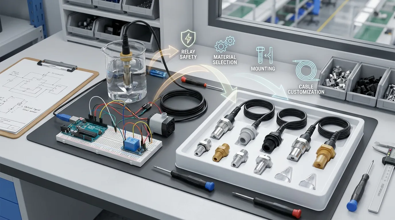
An Arduino setup is excellent for learning, proof-of-concept testing, aquarium top-off experiments, small reservoir alarms, and early product validation. It is not automatically ready for commercial equipment.
A productized sensor design must consider sealing, 케이블 스트레인 릴리프, connector choice, wetted material compatibility, 출력 유형, 장착 나사산, 반복성, production QC, and long-term exposure to water, 기름, 세정제, 냉각수, 증기, 또는 화학 물질. Industrial and OEM systems may also need NPN, PNP, 푸시-풀, analog 4–20 mA, custom cable length, panel mounting, 스테인리스 바디, PTFE 차체, or a compact prism geometry that fits a molded tank.
HojellyTek은 광전 광학 감지와 액체 수위 감지에 중점을 둔 선전의 제조업체이자 수출업체입니다. For production projects, our in-house R&D team can support OEM/ODM sensor configuration, housing material selection, connector and cable customization, and integration for appliances, 탱크, 산업 장비, and smart liquid monitoring products. Tuya/Smart Life integration may also be relevant for connected tank-level devices rather than a simple Arduino-only prototype.
우리는 미국으로 수출합니다, 우린, 그리고 인도, and we can help teams move from a DIY Arduino test to a manufacturable optical level sensing solution.
What to Confirm Before Ordering Sensors for a Real Build
Before moving beyond the breadboard, 이 세부사항들을 준비하세요:
| 요구 | 왜 중요한가 |
|---|---|
| 액체형 | 물, 기름, 냉각수, 세정제, and chemical mixtures may need different wetted materials |
| Sensor state | Confirm whether the control board needs wet = HIGH, 젖은 = 저음, NPN, PNP, or analog output |
| 공급 전압 | Arduino prototypes often use 5V, but production boards may use different logic rails |
| 장착 방식 | 스레드, 플랜지, top-entry, side-entry, or custom tank mounting changes sensor design |
| 차체 재질 | PSU, PTFE, 316 스테인리스 스틸, and glass serve different environments |
| 케이블 및 커넥터 | OEM products may need waterproof connectors, custom cable length, or molded leads |
| 펌프 제어 방법 | 릴레이, MOSFET, SSR, or controller input depends on pump voltage and load |
| 환경 | 응결, 진동, 온도, 거품, 비말, and cleaning cycles affect reliability |
Related Arduino and Single-Board Computer Builds
If you are building the same project with a different controller, 우리의 Raspberry Pi version. The wiring logic is similar, but GPIO voltage and input protection are different, so do not copy Arduino 5V wiring directly to a Raspberry Pi.
FAQ
How do I wire an arduino optical water level sensor?
Connect VCC to Arduino 5V, GND to Arduino GND, and digital OUT to a GPIO such as D2. Then read the pin with digitalRead() and confirm whether your module outputs HIGH or LOW when the prism tip is wet.
Does the optical water level sensor read HIGH when wet?
It depends on the module. Some output HIGH when wet; others output LOW when wet. Always test the dry and wet states in Serial Monitor before connecting a pump or relay.
Can Arduino control a pump from the sensor signal?
네, but the Arduino should control a relay module, MOSFET 드라이버, or motor driver. Do not power the pump directly from an Arduino pin.
Why does my relay click on and off quickly?
Relay chatter usually comes from unstable sensor readings, 파도, 비말, pump electrical noise, or missing debounce logic. Add a stable-state delay, minimum pump run/off time, cleaner wiring, and a proper power supply.
Can I use the same sensor for oil or chemicals?
항상 그런 것은 아닙니다.. The sensing principle may work, but wetted material compatibility is critical. 기름, 냉각수, 세정제, and chemicals may require PTFE, 316 스테인리스 스틸, 유리, or another suitable housing material.
When should I replace the DIY Arduino setup with an OEM sensor?
Move to an OEM sensor when the project becomes a product, 기기, 산업용 탱크, or customer-facing system. Request a quote from HojellyTek by WhatsApp or email with your liquid type, 전압, 출력, 장착, 차체 재질, 케이블, and expected use environment.