
Optical Level Sensor for Overflow Protection
Optical level sensor overflow protection helps stop tank overspill before it damages pumps, kāpata, papa, production equipment, or electrical panels. HojellyTek supplies optical high-level switches for overflow alarm circuits, pump cut-off circuits, valve shutoff systems, and tank-top high-level detection where a fast solid-state response is preferred over a mechanical float that may stick, honga, Piro, or fail to move freely.
For OEM equipment builders, tank system integrators, and industrial buyers, we configure photoelectric optical level sensors to match the liquid, turanga whakamau, control circuit, me te arorau pūoho.
Overflow Protection Capabilities
Our optical overflow protection service focuses on the alarm circuit, not generic tank monitoring. He ngāwari te whāinga: detect the high-level point quickly and send a reliable signal to the controller before the liquid reaches the spill point.
Typical configurations include:
- Optical high-level switch for tank overflow alarm
- Tank-top mounted optical level switch for overspill prevention
- Pump stop signal when liquid reaches the high point
- Solenoid valve close signal for inlet shutoff
- PLC input for high-level alarm logic
- Local buzzer, beacon, or panel indicator output
- Redundant high-high sensor for safety backup
- Whare OEM/ODM, aho, taura, tūhono, and output customization
For standard point-level detection, Ka taea hoki e ngā kaihoko te arotake i ā mātou pūoko taumata ōmata range and our pana taumata ira Ngā Kōwhiringa.
Why Overflow Damage Requires Fast High-Level Detection
A tank overflow is rarely only a liquid loss problem. In industrial and OEM systems, overspill can damage nearby motors, wiring terminals, pump cabinets, battery compartments, pūoko, packaging machines, papa whakahaere, and floor-mounted equipment. In chemical, hinu, kaikawe, waiwhakao, or fuel systems, overflow can also create cleanup costs, slip hazards, tāhaetanga, and process downtime.
The high-level alarm circuit must therefore react before the overflow line is reached. A mechanical float can work well in many basic tanks, but it depends on free movement. If the float arm sticks, the hinge fouls, the float rubs against the tank wall, or viscous liquid leaves residue, the switch may not change state at the correct level.
An optical high-level switch has no floating arm. The sensing tip is fixed at the alarm point. When liquid touches the prism tip, the sensor changes output state and sends a signal to the alarm, PLC, pump starter, or valve circuit. This makes it suitable for compact tanks, mokowā whāiti, puna iti, OEM cartridges, and systems where moving parts are a failure risk.
How the Optical High-Level Switch Works
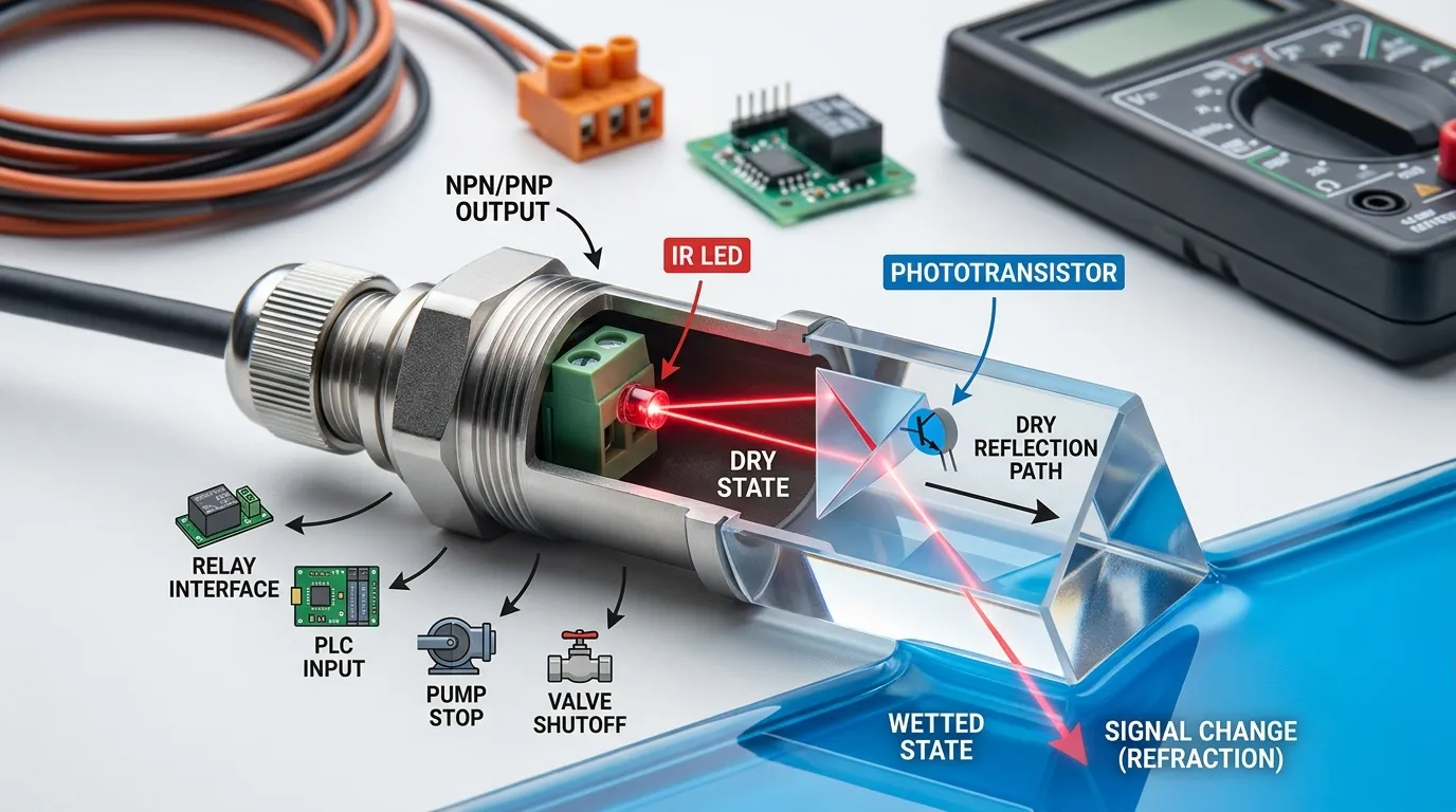
Inside the sensor tip, an infrared LED sends light into a prism. Ka whiwhi te whakaahua whakaahua i te rama whakaata. I te hau, the prism reflects the infrared beam back toward the receiver. Ina taupoki te wai i te pororua, ka huri te āhua tāhapa, less light returns to the receiver, and the electronic circuit switches output state.
This dry-versus-wetted detection principle is useful for overflow protection because the sensor does not need a long travel distance. The switching point is close to the physical sensor tip, so the high-level position can be placed near the top of the tank, below the overflow port or safety margin.
Depending on the buyer’s control system, the output can be configured for direct PLC input, low-voltage alarm boards, relay-interface circuits, or custom OEM electronics. NPN and PNP outputs are common for digital control systems. For continuous level systems, 4–20 mA may be used, but overflow protection usually uses a point-level switch because the circuit only needs a high-level alarm or cut-off signal.
High-Level Alarm vs Automatic Shutoff
Overflow protection should be designed around what must happen when the high-level point is reached.
He alarm-only circuit warns the operator through a buzzer, light tower, whakaaturanga, PLC alarm, or remote signal. This is suitable when human confirmation is required before stopping a process, or when the tank is part of a manual filling station.
He automatic shutoff circuit stops inflow without waiting for an operator. The sensor signal can stop a fill pump, close an inlet valve, disable a dosing pump, or trigger a controller interlock. This is preferred where overflow could quickly damage equipment or where filling may happen unattended.
Many industrial systems use both: the first high-level sensor triggers an alarm and stops filling, while a second high-high sensor acts as a redundant backup. The backup sensor should be wired into an independent alarm or safety logic where possible, not only into the same software condition.
For systems where the opposite failure mode is also important, such as preventing a pump from running without liquid, tirohia tā mātou papu parenga maroke taupānga, taupānga,.
High-Level Cut-Off Wiring Options
The wiring design depends on whether the sensor signal goes to a PLC, kōwae tānga, pūmana papu, valve driver, or alarm board. At RFQ stage, our team confirms supply voltage, momo huaputa, normal state, roanga taura, tūhono, and whether the signal should be active when dry or active when wetted.
| High-Level Function | Typical Signal Path | Common Output Choice | Circuit Action |
|---|---|---|---|
| Local overflow alarm | Sensor → alarm board → buzzer/beacon | NPN, PNP, atanga tānga rānei | Turns on visual or audible alarm when the tip is wetted |
| PLC high-level input | Sensor → PLC digital input | NPN, PNP rānei | PLC registers high-level condition and runs alarm logic |
| Pump cut-off | Sensor → relay/controller → pump starter | NPN/PNP with relay interface | Stops filling pump when liquid reaches high point |
| Valve shutoff | Sensor → controller/driver → solenoid valve | NPN/PNP or relay interface | Closes inlet valve to prevent further filling |
| Redundant high-high alarm | Second sensor → independent input or alarm | Separate digital output | Backup warning if first control stage fails |
| OEM control board | Sensor → custom PCB input | Customized transistor output or connector | Integrates overflow protection into equipment electronics |
For safety-critical systems, the sensor should not be treated as a standalone safety device unless the full control architecture is designed and validated for that purpose. The practical role of the optical switch is to provide fast, repeatable high-level detection to the alarm or cut-off circuit.
Redundancy With a Second High-High Sensor
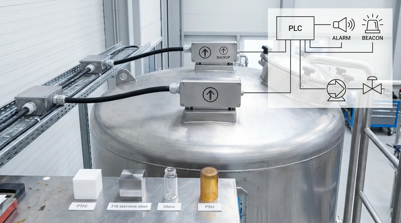
A single high-level optical sensor is often enough for simple equipment protection. Hoianō, a second sensor is recommended when overflow could damage expensive equipment, contaminate a production area, or create a hazardous spill.
The first sensor can be placed at the normal high-level alarm or filling stop point. The second sensor should be mounted slightly higher, below the true overflow point, as a high-high emergency signal. This second signal can activate a separate beacon, send a controller fault, disable the fill command, or require manual reset.
Redundancy helps protect against wiring faults, controller programming errors, blocked inlets, failed valves, incorrect operator settings, or a damaged primary sensor cable. It also gives maintenance teams a clearer fault diagnosis: if the high-high sensor triggers, the normal high-level stop did not control the filling event as expected.
Tank-Top Mounting for Overspill Protection
Overflow sensors are commonly installed from the tank top or upper side wall. Tank-top mounting keeps the sensing tip at the high-level point while the cable exits above the liquid area. It is often suitable for plastic tanks, puna whakamātao, kura inenga, kura wai, kura rekanoa, me ngā ipu wai OEM.
Key mounting choices include threaded mounting, whakatūnga paewhiri, compression-style installation, or custom OEM fitting. Thread size and sealing method should match the tank wall thickness, cap design, and service environment. Mō ngā taupānga maha, a compact optical sensor can be mounted where a float switch would not have enough clearance to move.
The sensing tip should be positioned below the spill point with enough margin for pump stop delay, valve closing time, liquid turbulence, huka, or wave movement. If the tank has strong splashing, a stilling tube, shielded location, software delay, or logic filtering may be considered, but the delay must not be so long that it defeats overflow protection.
For tank applications in the Indian market, we also support overflow sensor for tanks projects with OEM configuration and export support.
Materials and Specifications to Confirm
The sensor body and wetted parts must match the liquid. HojellyTek can discuss options such as PSU, PTFE, 316 tīra poapoa, or glass depending on media compatibility, here horoi, me ngā whakaritenga pūkaha.
I mua i te tono, Whakaū:
- Momo wai: wai, waiwhakao, hinu, Kora, matū, kaikawe, horoi horoi, wai whāranu rānei
- Ahakoa mārama te wai, tae, huka, piripiri, koti, or turbulent
- Rauemi kura me te mātotoru o te pakitara
- Kāhua whakamau: tank-top, pakitara taha, miro, harakeke, or custom fitting
- Huaputa e hiahiatia ana: NPN, PNP, atanga tānga, tairitenga, or OEM board signal
- Supply voltage required by the controller or alarm board
- Normal state: alarm when wetted or alarm when dry
- Roanga taura, momo tūhono, wire color requirements, and IP protection needs
- Whether a second high-high sensor is required
- Export destination and documentation requirements
For aggressive media, high-temperature areas, or hazardous-area projects, material and enclosure selection should be reviewed carefully before sample approval.
Optical vs Float for Overflow Alarm Circuits
| Pūwāhi Tīpakonga | Optical High-Level Switch | Whakakā Mānu Pūkaha |
|---|---|---|
| Ngā wāhanga nekehanga | No float arm or hinge | Requires float movement |
| Response point | Switches when liquid reaches prism tip | Depends on float travel and angle |
| Compact tank fit | Good for narrow OEM spaces | Needs movement clearance |
| Sticky liquid risk | No float to stick, but coating must be considered | Float can stick, Piro, tāmi rānei |
| Mounting flexibility | Suitable for tank-top or side mounting | Orientation and movement path are important |
| Alarm circuit use | Strong fit for high-level digital alarm | Common in simple tanks |
| Āwangawanga tautiakitanga | Check prism cleanliness and cable integrity | Check float movement, hingi, and buildup |
Overflow-Protection Checklist
Use this checklist when sending an RFQ for an optical level sensor overflow protection project:
- Define the exact high-level alarm point inside the tank.
- Confirm the distance between the alarm point and true overflow point.
- Decide whether the sensor should only trigger an alarm or also stop filling.
- Specify whether the output goes to a PLC, tānga, pūmana papu, valve driver, or alarm board.
- Whakaū NPN, PNP, atanga tānga, or custom output requirement.
- Decide if a second high-high backup sensor is needed.
- Confirm liquid compatibility with PSU, PTFE, 316 tīra poapoa, Karaehe, or other wetted materials.
- Provide mounting direction: tank-top, pakitara taha, cap-mounted, miro, or OEM custom.
- Check whether splashing, huka, koti, or turbulence may affect the high-level point.
- Confirm cable length, tūhono, wire exit direction, and sealing requirements.
- Confirm sample quantity, drawing needs, and production batch expectations.
5-Tukanga Ratonga Hipanga
1. Uiui
Send the tank drawing, momo wai, control circuit, high-level position, and target output. Photos of the tank-top area are useful when space is limited.
2. Spec me te Whakaritenga
Our engineering team confirms the sensing structure, papanga mākū, momo huaputa, miro whakamau, taura, tūhono, me te arorau pūoho.
3. Tauira
A sample can be prepared for fit testing, wet/dry switching verification, and controller compatibility checks.
4. Production and QC
I muri i te whakaūnga tauira, production follows the approved configuration. Key checks focus on appearance, waea, switching function, and customer-specific requirements.
5. Tukunga
Hei kaiwhakanao me te kawekawe Shenzhen, HojellyTek supports overseas buyers in the US, MATOU, Īnia, and other markets with export-ready communication and documentation coordination.
He aha te take e mahi tahi ai me HojellyTek
HojellyTek focuses on photoelectric optical sensing and liquid level detection, me te R ā-whare&D and OEM/ODM support for sensor structure, papanga, taura, tūhono, and output customization. We support buyers who need practical engineering discussion before production, not only a catalog part number.
For smart tank or connected equipment projects, our team can also discuss Tuya and Smart Life related integration where it is relevant to the full device design.
FQ
How does optical level sensor overflow protection work?
Optical level sensor overflow protection uses an infrared LED, whakawhitiwhiti whakaahua, and prism tip to detect when liquid reaches the high-level point. Ina huri te pito mai i te maroke ki te mākū, the output switches and can trigger an alarm, pump stop, valve close, or PLC high-level signal.
Is an optical switch better than a float switch for overflow alarms?
For compact tanks or sticky-float risk, an optical switch is often better because it has no moving float arm. It switches at the prism tip instead of relying on mechanical travel. Liquid coating, hototahitanga matū, and mounting position still need to be checked.
Can the sensor automatically stop a pump?
Āe, if the control circuit is designed for it. The optical sensor output can go to a PLC, kōwae tānga, pūmana papu, or interlock circuit that stops the fill pump when the high-level point is reached.
Should I use one sensor or two sensors?
Use one high-level sensor for basic overflow alarm or filling stop. Add a second high-high sensor when overflow could damage expensive equipment, create safety issues, or require backup alarm logic.
Where should the sensor be mounted?
Most overflow applications use tank-top or upper side-wall mounting. The prism tip should sit below the actual overflow point with enough margin for pump delay, valve closing time, tārewa, and liquid movement.
He aha ngā mōhiohio me tuku e au mō tētahi whakahua?
Tukua te momo wai, tank drawing or photos, turanga whakamau, ngaohiko puto, momo huaputa, normal alarm state, cable or connector needs, and whether the sensor controls an alarm, mapu, kōrere, PLC, or backup high-high circuit.
Tonoa he Kīanga
Send your overflow protection drawing, momo wai, control circuit, and target mounting method to HojellyTek by WhatsApp or email. Our team can recommend an optical high-level switch configuration for alarm-only, whakaweto aunoa, or redundant high-high overflow protection.