
Optical Level Sensor for Pump Dry-Run Protection
Optical level sensor pump dry run protection helps stop a pump before liquid falls below the safe suction point and causes burnt seals, damaged impellers, Oorverhitting, or air intake. HojellyTek supplies photoelectric optical level sensors for compact, fast-response low-level cut-off circuits in tanks, Reservoirs, Koelmiddelsisteme, Oliehouers, and OEM pump assemblies.
Use this page to specify the sensor, Bedradinglogika, mounting point, and reset behavior for a reliable dry-run prevention circuit.
Optical Pump Dry-Run Protection Capabilities
Vir pompbeskerming, the sensor is not just a level indicator. It becomes the low-level decision point in the control circuit: when the liquid drops below the cut-off height, the output changes state and the controller stops the pump.
HojellyTek supports dry-run protection projects that may include:
- Optical point-level detection at the minimum safe liquid level
- Low-level cut-off output for PLC, Relaisbord, Pompbeheerder, or VFD input
- NPN, PNP, or analog signal options depending on the control system
- NO/NC logic selection based on fail-safe requirements
- Compact prism-tip sensors for small tanks and OEM pump modules
- Wetted material selection such as PSU, PTFE, 316 Vlekvrye staal, of glas
- Threaded or custom mounting for tank wall, reservoir side, or chamber installation
- OEM/ODM customization for housing, Kabel, Konnektor, gare, en uitsetlogika
For a general product overview, sien ons optiese vlaksensor omvang. For a ready product reference, review the Foto-elektriese vloeistofvlakskakelaar.
Why Dry-Run Cut-Off Must Happen Before the Pump Runs Empty
A pump does not need to run dry for long before damage begins. When liquid is no longer present at the suction side, the pump may lose cooling, Smeermiddel, and hydraulic load. The result can be burnt mechanical seals, damaged impellers, overheated wetted parts, cavitation, Vibrasie, or total pump failure.
A dry-run protection circuit must therefore answer one practical question:
At what exact liquid level should the pump be forced OFF?
An optical level sensor is mounted at that cut-off point. When liquid covers the prism tip, the sensor sees the “wet” state. When liquid drops below the tip, the optical path changes and the output switches quickly. The control circuit then removes the pump run signal, opens a relay, disables a VFD input, or sends a stop command to the pump controller.
This is different from general tank monitoring. In dry-run protection, the sensor position, Uitsetlogika, and reset behavior must be designed around pump safety.
How the Optical Sensor Detects Wet and Dry States
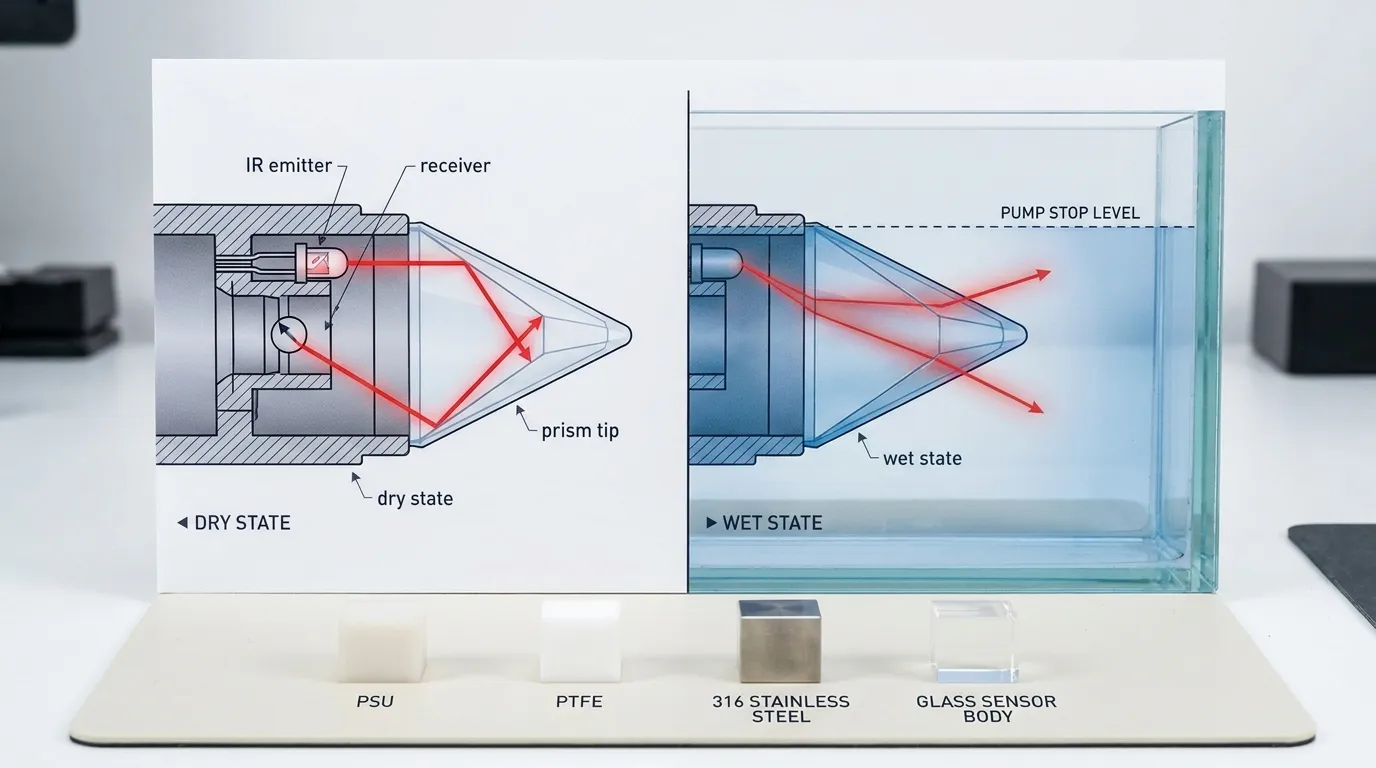
A photoelectric level sensor uses an infrared LED, 'n fototransistor, and a shaped optical prism at the sensing tip. In die lug, infrared light reflects internally inside the prism and reaches the receiver. When the prism is covered by liquid, the refractive condition changes and less light returns to the receiver. The electronics convert this optical change into a digital output.
This design has no float arm, magneet, Skarnier, or moving mechanical part inside the liquid. That is important for pump cut-off applications where a slow, Vasgevang, or tilted float can delay the stop signal. Optical sensing is especially useful for compact reservoirs, Nou kamers, OEM-toerusting, Koelmiddeltenks, dosing systems, water containers, and sealed pump modules where mechanical switches may be too large.
A dry-run circuit normally uses the sensor as a point-level switch. For related point detection applications, sien ons Puntvlakskakelaar Bladsy.
Low-Level Cut-Off Wiring for Pump Control
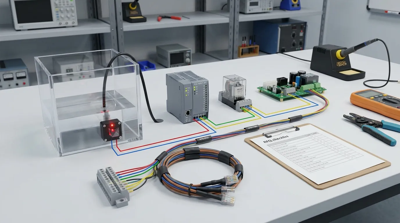
The sensor output should be matched to the control input, not chosen only by sensor shape. Voor bestelling, confirm whether your pump system uses a relay coil, PLC digital input, VFD dry contact input, transistor input, or custom PCB.
Common control arrangements include:
- Sensor to PLC input: the PLC reads wet/dry state and controls the pump contactor or VFD.
- Sensor to relay module: the sensor drives a relay that opens the pump enable circuit.
- Sensor to pump controller: the controller receives a low-level alarm or run-permit signal.
- Sensor to VFD input: the dry-run signal disables drive operation or triggers a fault input.
- Sensor to OEM PCB: the signal is read directly by the product control board.
The safest design is usually a “run permit” logic. The pump is allowed to run only when the sensor confirms liquid is present. When the sensor becomes dry, the run permit is removed.
Wiring Logic Table for Dry-Run Protection
| Liquid state at sensor tip | Sensor output logic | Controller interpretation | Pump action | Beste gebruiksgeval |
|---|---|---|---|---|
| Nat / liquid present | Run-permit signal active | Safe liquid level available | Pump allowed to run | Standard low-level protection |
| Droog / liquid below tip | Run-permit signal removed | Dry-run risk detected | Pump stops or cannot start | Fail-safe pump cut-off |
| Wet after refill | Signal active again | Liquid restored | Auto-reset or manual reset depending on logic | Simple reservoirs or controlled refill systems |
| Dry with latch enabled | Trip remains active | Fault must be acknowledged | Pump remains OFF | High-value pumps, chemical dosing, unattended systems |
| Wet/dry unstable near wave line | Signal may change repeatedly | Chatter risk | Use delay, Hysterese, or stilling tube | Agitated tanks or small chambers |
| Sensor/cable fault | Signal depends on wiring design | Fault or no run permit | Pump should stop in fail-safe design | Critical pump protection circuits |
For most dry-run applications, specify the desired wet/dry output state clearly. The factory can help match NPN, PNP, NEE / NC, or analog output to your controller design.
Fast Optical Response vs Sluggish Float Switches
Float switches are common, but they are not always ideal for pump dry-run protection. A float needs physical movement, space to swing, and correct orientation. In small tanks, oily liquid, narrow pump chambers, or equipment with vibration, the float may respond slowly or stick.
An optical sensor responds directly at the sensing tip. When the liquid uncovers the prism, the optical state changes without waiting for a float arm to drop. This makes the cut-off point more repeatable and compact.
Optical dry-run sensing is useful when the buyer needs:
- A precise low-level cut-off height
- Compact mounting inside a small reservoir
- Fast switching at the minimum safe level
- No moving parts in the liquid
- OEM-friendly housing and cable customization
- Cleaner signal integration with a PCB, PLC, of pompbeheerder
Nietemin, the sensor must still be selected correctly. Foaming liquid, heavy coating, crystallization, or thick residue may require material selection, tip placement, Skoonmaaktoegang, or an additional protection method.
Latch, Vertraging, and Auto-Reset Logic
The sensor output is only one part of the protection system. The control logic determines what happens after a dry condition is detected.
Auto-reset logic allows the pump to restart after liquid returns above the sensor tip. This can work for simple water tanks, refill reservoirs, or systems where restart is safe and expected.
Latch logic keeps the pump OFF after a dry-run trip until an operator or controller resets the fault. This is better for expensive pumps, chemical systems, industrial dosing, unattended equipment, or systems where repeated dry starts could cause damage.
Delay logic prevents nuisance trips from waves, gespat, Borrels, or momentary liquid movement around the sensor. A short controller delay can confirm that the sensor is truly dry before stopping the pump. A restart delay can also prevent short cycling after refill.
The page topic is not pump maintenance; the key point is control design: define whether the dry output should stop the pump immediately, stop after a verified delay, latch until manual reset, or auto-reset after the wet signal returns.
Mounting the Sensor at the Cut-Off Point
The sensor should be installed at the minimum safe liquid level, not simply near the bottom of the tank. The correct height depends on the suction port, pump intake geometry, vortex risk, required reserve volume, and whether the tank surface moves during operation.
Mounting guidance:
- Place the prism tip at the liquid height where the pump must stop.
- Keep the tip clear of tank walls, Hoeke, sediment zones, and dead areas.
- Avoid locations where bubbles or splashing repeatedly expose and cover the tip.
- For agitated tanks, consider a stilling tube or protected sensing chamber.
- Vir sywandinstallasie, confirm thread type, Seëlmetode, and cable direction.
- For chemically aggressive liquids, choose compatible wetted materials.
- For oil or fuel applications, confirm optical response and material compatibility before mass production.
For overflow and high-level protection using similar optical sensing principles, sien ons Oorloopbeskermingsensor Bladsy.
Dry-Run Protection Checklist Before RFQ
| Item to confirm | Why it matters for the cut-off circuit |
|---|---|
| Vloeistoftipe | Water, Koelmiddel, Olie, Brandstof, Chemiese, or mixed liquid affects material and optical behavior |
| Minimum safe level | Determines the exact sensor mounting height |
| Tank or chamber material | Affects thread, Verseëling, and mounting method |
| Control input type | PLC, Aflos, VFD, Pompbeheerder, or PCB requires different output matching |
| Uitsetvoorkeur | NPN, PNP, NEE / NC, or analog output must match the circuit |
| Reset logic | Auto-reset or latch reset changes pump restart behavior |
| Delay requirement | Prevents false trips from waves, Vibrasie, Borrels, or splashing |
| Nat materiaal | PSU, PTFE, 316 Vlekvrye staal, or glass should match liquid and environment |
| Cable and connector | Important for OEM assembly, Toegang tot diens, and waterproof routing |
| Installation orientation | Side mount, vertical mount, chamber mount, or custom holder affects reliability |
5-Stapdiensproses
1. Navraag
Send your pump type, Tenktekening, Vloeibare tipe, control input, and required cut-off level by WhatsApp or email. Foto's, Bedradingdiagramme, or PCB input details help our engineers respond faster.
2. Spesifikasie en Aanpassing
Our team confirms the optical sensor type, natgemaakte materiaal, Uitsetlogika, gare, Kabel, Konnektor, en monteringsrigting. Vir OEM/ODM-projekte, housing and harness details can be adjusted to fit the equipment design.
3. Voorbeeld
A sample can be prepared for wet/dry signal testing in your actual liquid and controller circuit. This step is important for checking reset behavior, low-level stop timing, and mounting position.
4. Produksie en kwaliteitsbeheer
Na die goedkeuring van die monster, Produksie volg die bevestigde spesifikasie. QC focuses on optical switching function, Uitsetgedrag, Bedrading, Verseëling, and appearance based on the agreed configuration.
5. Skeepsvaart
HojellyTek exports optical liquid level sensor products from Shenzhen to customers in the US, ONS, Indië, en ander markte. Packaging and documentation are arranged according to the project requirements.
Requirements and Specs to Confirm
For a pump dry-run protection project, confirm these details before ordering:
- Vloeistofnaam en konsentrasie
- Normal and minimum liquid level
- Tank wall thickness and mounting space
- Required thread or installation structure
- Sensor body material and prism/tip material
- Voorsieningsspanning wat deur die beheerpaneel benodig word
- Uitsettipe: NPN, PNP, 4–20 mA, or other interface
- Wet-state and dry-state output preference
- Kabellengte, Konnektor, and wire color requirement
- Whether the pump should auto-reset or stay latched OFF
- Whether the application needs Tuya/Smart Life integration for remote tank monitoring
Do not guess the wiring logic at installation time. The cut-off circuit should be specified before production so the sensor output and controller input match correctly.
Optical Sensor vs Other Dry-Run Protection Methods
| Metode | Strength | Beperking | Best fit |
|---|---|---|---|
| Optiese vlak sensor | Fast point-level response, Kompakte, no moving float | Needs correct material and clean sensing tip | OEM tanks, Reservoirs, compact pump systems |
| Vlotskakelaar | Simple and familiar | Can be slow, bulky, tilted, of vasgevang is | Larger tanks with enough float movement space |
| Druk skakelaar | Can infer low suction or discharge condition | May not detect actual tank level directly | Pump systems needing pressure-based backup |
| Flow switch | Detects actual flow loss | May react after flow has already failed | Pipeline protection and secondary confirmation |
| Current sensing | Detects abnormal motor load | Requires tuning and may vary by pump | Motor protection layer, not precise level cut-off |
For many compact systems, the optical sensor is the most direct low-level cut-off device. For complex industrial systems, it can also be combined with pressure, Vloei, or current monitoring for layered protection.
Hoekom Werk Met HoJellyTek
HojellyTek is a Shenzhen manufacturer and exporter focused on photoelectric optical sensing and liquid level sensor development. Met in-huis R&D and OEM/ODM capability, we help buyers match the sensor body, output circuit, Kabel, and mounting design to the pump protection application.
Our team supports practical engineering questions: nat/droë logika, NPN/PNP selection, thread options, Materiaalversoenbaarheid, and sample testing. Instead of offering one generic switch for every pump, we help define the cut-off point and control behavior before production.
Vrae
Can an optical level sensor prevent pump dry-running?
Ja. When mounted at the minimum safe liquid level, the sensor detects when liquid drops below the prism tip and sends a dry-state signal to stop the pump through a PLC, Aflos, VFD, of pompbeheerder.
What does optical level sensor pump dry run protection mean?
It means using an optical point-level sensor as the low-level cut-off device in the pump control circuit. The pump runs only when the sensor confirms liquid is present and stops when the sensor detects a dry condition.
Should the pump restart automatically after the tank refills?
It depends on risk. Auto-reset is suitable for simple refill tanks. Latch/manual reset is safer for expensive pumps, Chemikalieë, unattended systems, or applications where repeated dry starts could damage the equipment.
Is an optical sensor faster than a float switch?
In baie kompakte tenks, Ja. An optical sensor changes state at the prism tip without waiting for a float arm to move. This gives a more direct cut-off signal at the selected liquid level.
Where should the sensor be installed for dry-run protection?
Install it at the minimum safe cut-off height above the pump suction risk point. Avoid bubbles, Sediment, Turbulensie, and locations where the sensor tip may be repeatedly splashed instead of steadily wetted.
What output should I choose for a pump controller?
Choose the output based on the control input. PLCs often use NPN or PNP digital inputs, relay modules may need NO/NC logic, and some systems require analog or custom PCB input. Confirm this during RFQ.
Request a Quote for Pump Dry-Run Sensor Protection
Send your tank drawing, Vloeibare tipe, pump control method, wiring input, and required cut-off level to HojellyTek by WhatsApp or email. We will recommend an optical level sensor configuration for your dry-run protection circuit, including output logic, Materiaal, gare, Kabel, and sample testing options.