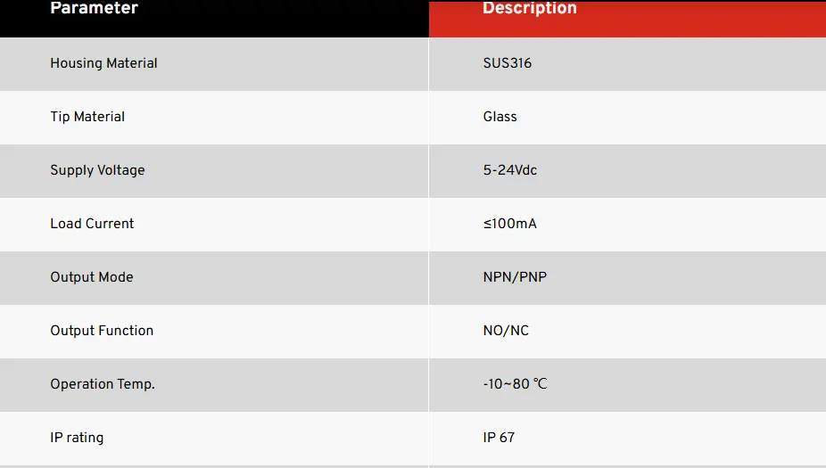
Advantages of Fiber Optic Liquid Level Sensors
In the fast-paced world of industrial automation and fluid management, precision and safety are no longer just operational goals—they are absolute necessities. For decades, engineers have relied on traditional mechanical, capacitive, and ultrasonic tools to monitor tank levels. However, as industries push the boundaries into harsher environments, extreme temperatures, and highly volatile materials, conventional electrical sensors frequently fall short.
Enter the fiber optic liquid level sensor.
By utilizing light instead of electricity to detect the presence or absence of liquids, this innovative technology has completely revolutionized industrial fluid management. Whether you are dealing with cryogenic temperatures, highly explosive chemicals, or environments plagued by electrical noise, optical technology provides a robust, reliable, and elegant solution.
In this comprehensive guide, we will explore the underlying physics of optical sensing, unpack the distinct advantages of adopting this technology, compare it to traditional methods, and highlight its most critical applications across modern industries.
The Science of Light: How Optical Sensors Detect Liquid
To fully appreciate the benefits of a fiber optic liquid level sensor, it is important to understand the fascinating physics that make it work. Unlike mechanical floats that can jam or electrical probes that can short-circuit, a fiber optic sensor operates purely on the behavior of light particles (photons) traveling through a glass or plastic core.
Total Internal Reflection in Fluid Detection
The most common type of optical point-level sensor relies on a principle known as total internal reflection in fluid detection.
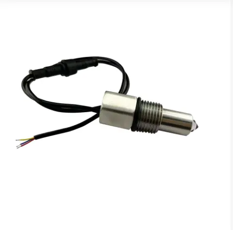
Here is how it works in practice: The sensor consists of an optical fiber connected to a transparent tip, which is usually shaped like a cone or a prism. An LED or laser sends a beam of light down the fiber optic cable into this prism.
- When the sensor is in the air: The light hits the inside of the prism. Because the refractive index of the glass is significantly different from the refractive index of the surrounding air, the light is perfectly reflected inside the prism and bounces back up the fiber to a receiver.
- When the sensor is submerged: As the liquid level rises and touches the prism, the environment changes. Liquids have a refractive index much closer to that of the glass prism. This phenomenon, known as refractive index based liquid level detection, causes the light to stop reflecting internally. Instead, the light escapes (refracts) into the liquid.
The receiver instantly detects this sudden drop in returning light and triggers an output signal indicating that the liquid has reached that specific level. It is a binary, fail-safe mechanism that happens at the speed of light.
How Fiber Bragg Grating Sensors Work in Continuous Measurement
While prism-based sensors are excellent for detecting single points (like high-level alarms or low-level shutoffs), some industrial applications require continuous, real-time level monitoring across the entire height of a tank. To grasp how this is achieved optically, we must look at how fiber bragg grating sensors work.
A Fiber Bragg Grating (FBG) is a microscopic alteration made directly inside the core of an optical fiber. This alteration creates a periodic variation in the refractive index, acting like an invisible, internal mirror that reflects only one specific wavelength (color) of light while letting all other wavelengths pass through.
When a hydrostatic pressure system utilizes an FBG sensor placed at the bottom of a liquid tank, the weight of the fluid applies physical strain to the sensor. As the liquid level increases, the pressure increases, physically stretching or compressing the fiber by microscopic amounts. This physical strain changes the spacing of the grating, which in turn shifts the specific wavelength of light being reflected. By measuring this exact spectral shift, the interrogator system can calculate the precise liquid level with astonishing accuracy.
The Unmatched Advantages of Fiber Optic Liquid Level Sensors
Why are engineers and plant managers increasingly moving away from legacy systems in favor of optical technology? The transition is driven by a unique set of benefits that solve some of the most stubborn engineering challenges in modern fluid management.
1. Absolute Safety in Hazardous Environments
When dealing with highly flammable petrochemicals, solvents, or natural gases, introducing any form of electrical current into a storage tank poses a severe risk. Even a microscopic spark from a faulty wire can trigger a catastrophic explosion.
This is exactly why use fiber optics in hazardous areas has become a best practice in the oil, gas, and chemical sectors. Fiber optics carry photons, not electrons. There is zero electrical current running through the sensor probe located inside the tank. This provides inherently safe operations.
For facilities requiring intrinsically safe level measurement for volatile liquids, fiber optics eliminate the need for heavy, expensive explosion-proof housings and complex safety barriers. Furthermore, spark-free level sensing for fuel storage guarantees that no matter what physical damage occurs to the sensor array inside the tank—whether it is crushed, severed, or degraded—it is physically impossible for the sensor to generate a spark or thermal ignition source.
2. Complete Immunity to Electrical Noise
Modern industrial plants are dense jungles of heavy machinery, massive electric motors, variable frequency drives (VFDs), and high-voltage power lines. This equipment generates massive amounts of Electromagnetic Interference (EMI) and Radio Frequency Interference (RFI).
Traditional electronic liquid level sensors often pick up this interference, leading to noisy signals, false alarms, and erratic readings. Because optical fibers are made of pure silica glass or specialized polymers, they are entirely non-conductive. This makes them perfectly emi immune sensors for industrial automation.
The advantages of non-conductive level probes extend beyond just EMI immunity. They are also unaffected by ground loops, static electricity buildup from flowing liquids, and even nearby lightning strikes. The light signal remains pure, stable, and completely isolated from the chaotic electrical environment of the factory floor.
3. Long-Distance Monitoring Without Signal Degradation
In massive tank farms, offshore platforms, or extensive water treatment facilities, the control room where data is analyzed can be located kilometers away from the actual storage tanks. When traditional electrical signals are sent over long distances, the voltage drops, and the signal degrades, requiring expensive amplifiers or repeaters.
Optical technology excels at long-haul data transmission. Remote fluid monitoring using light signals allows the active electronic components (the light source and receiver) to be housed in a safe, climate-controlled control room, while the passive fiber optic liquid level sensor is installed out in the field. The light signals can travel through standard fiber optic telecommunications cables for miles without any meaningful loss of signal integrity or accuracy, making site-wide integration incredibly efficient.
4. Seamless Scalability with Multipoint Arrays
Traditional single-point level switches require individual wiring for every single sensor. If you want to monitor low, medium, and high levels in a single tank, you typically have to run three separate cables, deal with three separate entry points into the tank, and manage three distinct signals.
A major breakthrough in optical sensing is the ability to perform multipoint sensing using fiber optic arrays. Because we can use different wavelengths of light or time-division multiplexing, manufacturers can string multiple measurement points along a single, continuous strand of optical fiber.
This means you can drop one single fiber optic cable into a deep well or tall storage tank and measure the liquid level at 10, 20, or even 50 different depth increments. This reduces installation complexity, minimizes tank penetrations (which is crucial for pressurized vessels), and drastically lowers cabling costs.
Optical vs. Traditional Technologies: A Comparative Analysis
To truly understand the value of optical fluid detection, it is highly beneficial to compare it directly against the traditional legacy transmitters that have dominated the market for decades.
Optical vs Ultrasonic Level Transmitters
Ultrasonic sensors operate by emitting a high-frequency sound wave from the top of the tank down toward the liquid. The sound wave bounces off the liquid surface and returns to the sensor. By calculating the time it took for the echo to return, the system determines the liquid level.
While popular, ultrasonic sensors have several distinct weaknesses that optical sensors overcome:
- Foam and Turbulence: Ultrasonic sound waves are easily absorbed or scattered by heavy foam, aggressive surface turbulence, or floating debris. Optical point sensors, utilizing total internal reflection, cut right through surface foam and only trigger when the actual liquid density hits the prism.
- Vapor and Temperature Gradients: Sound travels at different speeds depending on the temperature and density of the air it is passing through. In a closed tank with heavy chemical vapors or shifting temperature gradients, the speed of sound changes, causing highly inaccurate readings. Optical vs ultrasonic level transmitters is a one-sided battle here; light is not affected by air temperature gradients or vapor density, ensuring reliable operation regardless of the headspace atmosphere.
- Echo Interference: Internal tank structures, such as ladders, agitators, or heating coils, can create false echoes that confuse ultrasonic sensors. A fiber optic liquid level sensor is immune to acoustic echoes because it measures by direct contact or physical hydrostatic strain.
Optical vs Capacitive Level Measurement Accuracy
Capacitive level sensors measure the electrical capacitance between a probe and the tank wall. The capacitance changes as the liquid (which acts as a dielectric material) displaces the air in the tank.
The fundamental flaw with capacitive measurement is its reliance on the liquid's dielectric constant remaining perfectly stable.
- Fluid Composition Changes: If a tank is used to store different types of chemicals, or if the moisture content in an oil tank changes, the dielectric constant fluctuates. When this happens, a capacitive sensor will output an incorrect level reading unless it is manually recalibrated.
- Temperature Variations: Even if the fluid remains the same, a severe change in temperature can alter the liquid's dielectric properties, leading to measurement drift.
When analyzing optical vs capacitive level measurement accuracy, optical technology stands out because it does not rely on electrical properties. Refractive index based liquid level detection is remarkably stable. The refractive index of water or oil does not change enough with temperature variations to prevent the light from escaping the glass prism. Therefore, a fiber optic sensor does not require constant recalibration when the fluid temperature changes or when switching between similar liquid types.
High-Stakes Industrial Applications
Because of their unique characteristics—extreme safety, EMI immunity, and high accuracy—fiber optic liquid level sensors are rapidly becoming the standard in sectors where failure is not an option.
High Temperature Oil and Gas Tank Monitoring
The petroleum industry presents some of the most aggressive environments on earth. Deep-well extraction, heavy crude oil storage, and refining processes often involve extreme heat. Standard electronic sensors rely on silicon-based microchips and solder joints, which begin to degrade or melt at temperatures exceeding 150°C (300°F).
Fibers, however, are made of drawn glass. Fused silica has a melting point of over 1,600°C. By utilizing specialized metal coatings (like gold or copper) instead of standard plastic jackets, optical sensors can be engineered to withstand highly destructive heat. High temperature oil and gas tank monitoring is now vastly safer and more reliable. Operators can deploy FBG strain sensors or optical point sensors directly into refining vessels, hot bitumen tanks, and high-pressure separators without fear of the electronics cooking and failing.
Measuring Cryogenic Liquids with Optical Fibers
On the opposite end of the temperature spectrum lies the booming cryogenic industry, including the storage and transport of Liquefied Natural Gas (LNG at -162°C), liquid oxygen, and liquid hydrogen.
Traditional electrical cables become incredibly brittle at these temperatures. Insulation cracks, moisture enters, and the electronics seize. Furthermore, any heat generated by an electrical sensor can cause localized boiling of the cryogenic fluid, creating bubbles that disrupt accurate measurement.
Because optical sensors generate zero heat and glass retains its structural integrity at profoundly low temperatures, measuring cryogenic liquids with optical fibers is highly effective. The sensors can be fully submerged in liquid hydrogen without altering the fluid's state or risking catastrophic failure due to material embrittlement.
Aerospace and Aviation Fluid Management
In aviation, every ounce of weight matters, and electrical interference can disrupt flight-critical navigation systems. Aircraft utilize fiber optics for fuel tank monitoring because the glass fibers are incredibly lightweight compared to heavy copper wiring bundles. Additionally, the spark-free nature of the sensors ensures absolute safety inside jet fuel tanks, while their immunity to EMI means they will not interfere with or be affected by the aircraft's powerful radar and communication systems.
Semiconductor Manufacturing and Chemical Processing
Semiconductor fabrication plants use highly corrosive acids and ultra-pure water. Standard metal probes can corrode or leach metal ions into the ultra-pure water, ruining millions of dollars' worth of silicon wafers. Fiber optic liquid level sensors can be manufactured entirely from inert materials like quartz glass, sapphire, or Teflon. They provide accurate measurements without reacting with strong acids or contaminating pristine manufacturing environments.
Best Practices: Installation and Maintenance
While an optical liquid level sensor is inherently robust and contains no moving parts to wear out, proper installation and ongoing care are vital to ensuring decades of flawless operation.
Smart Installation Guidelines
- Mind the Bend Radius: The most common mistake made when installing any fiber optic sensor is bending the cable too sharply. Optical fibers can break if bent beyond their minimum bend radius. Even if the glass does not snap, severe bends can cause "macrobending losses," where light leaks out of the cable before it reaches the sensor tip, resulting in weak signals. Always follow the manufacturer's specifications for routing cables.
- Strategic Positioning: For point-level prism sensors, install the probe in an area of the tank where liquid flows freely but is protected from direct impacts. If the tank is filled from the top, do not place the sensor directly under the fill pipe where splashing liquid could trigger false high-level alarms. Use a stilling well (a protective tube with holes) if the liquid surface is excessively turbulent.
- Cable Protection: While the glass fiber is protected by cladding and jacketing, it should still be shielded from physical crushing, heavy foot traffic, or wildlife (rodents can sometimes chew through standard cabling). Running the fiber through conduit in high-traffic areas is always recommended.
Routine Maintenance of Optical Liquid Sensors
One of the most attractive features of optical technology is its low-maintenance profile. Because there are no mechanical floats to un-jam and no electrical calibrations required, the preventative maintenance schedule is surprisingly light. However, ignoring maintenance entirely can lead to operational hiccups.
- Keep the Optics Clean: The fundamental principle of refractive index based liquid level detection relies on the glass prism making direct physical contact with the liquid. If you are monitoring highly viscous liquids, sludge, or water with high biological content (like algae), a film can build up on the sensor tip over time. If a thick layer of dried sludge covers the prism, the sensor might continuously read "wet" even when the liquid level drops. Routine maintenance of optical liquid sensors should involve periodically removing the probe and wiping the optical tip with a soft cloth and a suitable solvent (like isopropyl alcohol).
- Inspect Connections: The weakest points in any optical network are the connectors (the points where the fiber plugs into the interrogator or transmitter). Dust, dirt, or oil on the end-face of a fiber connector can scatter the light and severely weaken the signal. If a sensor suddenly stops responding or reports a weak signal, use a specialized fiber optic cleaning pen to clean the connectors before assuming the sensor is broken.
- Monitor Interrogator Health: While the sensor in the field is passive, the interrogator unit in the control room contains the active light source (LED or laser). Over many years, the light output of an LED can naturally dim. Modern interrogators often have diagnostic software that alerts operators to signal degradation. Pay attention to these alerts to schedule replacements long before a failure occurs.
The Future of Fluid Monitoring is Built on Light
As industries evolve, the environments in which we operate are becoming more extreme, the safety regulations are becoming more stringent, and the demand for real-time data is growing exponentially. In this landscape, legacy electrical and mechanical sensors are being pushed to their absolute limits.
The transition to the fiber optic liquid level sensor is not just a minor upgrade; it represents a fundamental shift in how we approach industrial safety and precision. By harnessing the power of light, facilities can achieve what was once thought impossible: absolute immunity to electrical noise, perfectly spark-free operations in highly explosive zones, and reliable performance in both the deepest freezes of cryogenics and the searing heat of petrochemical refining.
Whether you are looking to deploy multipoint sensing using fiber optic arrays for a massive tank farm, seeking the most reliable spark-free level sensing for fuel storage, or simply wanting to eliminate the constant recalibration headaches associated with capacitive probes, optical technology offers an elegant, future-proof solution.
Understanding the principles of total internal reflection and how fiber bragg grating sensors work empowers plant engineers to make informed decisions that protect their infrastructure, safeguard their personnel, and optimize their fluid management systems. As the costs of fiber optic components continue to decrease and integration becomes easier, the advantages of adopting light-based sensing are simply too substantial to ignore.
The next time you are faced with a challenging fluid monitoring application, look beyond the limitations of standard electronics. Look toward the speed, safety, and unwavering precision of light.