
How to Install a Neptune Systems Optical Level Sensor
If you are searching for how to install neptune systems optical level sensor, the practical job is simple: mount the OS-1 or OS-1-M at the correct water height in the reef sump return chamber, secure it so the sensing tip cannot move, connect it to the Apex/FMM input, then configure the ATO outlet with delay and safety rules before trusting it with a pump.
This guide focuses on the installation details that actually affect reliability: sensor height, magnetic holder placement, OPEN/CLOSED behavior, false triggers, salt creep, cleaning, and redundant sensor planning.
Parts Needed for an OS-1 / OS-1-M Reef Sump Installation
| Part | Purpose | Installation Note |
|---|---|---|
| Neptune Systems OS-1 optical sensor | Detects wet/dry water level state | Usually used with a bracket or through-wall style holder |
| Neptune Systems OS-1-M optical sensor with magnetic mount | Easier sump-wall mounting | Useful when you do not want to drill or fabricate a holder |
| Apex / FMM module | Reads the optical sensor input | The sensor must be assigned correctly in Apex Fusion |
| ATO pump or dosing pump | Adds freshwater when sump level drops | Must be controlled with delay and maximum-run protection |
| ATO reservoir | Freshwater supply | Add a low-level protection sensor if possible |
| Cable clips or routing accessories | Keeps wire away from splash and maintenance tools | Avoid cable strain near the sensor body |
| Cleaning cloth / soft brush | Removes salt creep and film | Do not scratch the sensing prism |
| Redundant high-level sensor | Backup against overfill | Mount slightly above the normal water line |
Step 1: Choose the Mounting Height in the Return Chamber
Install the optical sensor in the return pump chamber, not in a chamber where baffles keep the water level constant. The return chamber is where evaporation shows up first, so it gives the ATO system a meaningful low-water signal.
Set the OS-1 or OS-1-M sensing tip at the normal operating water line you want the ATO to maintain. When the water drops below that point, the sensor reports a dry/low condition, and the Apex can turn on the ATO pump. When freshwater raises the level back over the sensor tip, the sensor reports wet/normal, and the pump should stop.
Do not mount the sensor too close to the return pump intake, turbulent drain flow, skimmer bubbles, or a waterfall between sump chambers. Bubbles and ripples can interrupt the optical signal and cause chatter. A stable side wall of the return chamber is usually the best location.
Step 2: Install the Magnetic Mount or Holder
For an OS-1-M, clean both sides of the sump wall before placing the magnetic holder. Slide the sensor so the optical tip points into the water and sits level with the target water height. Tighten or lock the holder enough that routine maintenance will not shift it.
For an OS-1 without the magnetic holder, use a secure bracket, acrylic holder, or through-wall style mount. The goal is not just “holding the sensor”; it is preventing tiny height changes. A few millimeters of movement can change when the ATO pump starts or stops.
Keep the sensing face exposed. Do not push the prism tip against acrylic, silicone seams, algae film, tubing, snails, or macroalgae. Optical point-level sensors need a clean optical path around the prism.
Step 3: Understand How the Optical Tip Reads Wet vs Dry
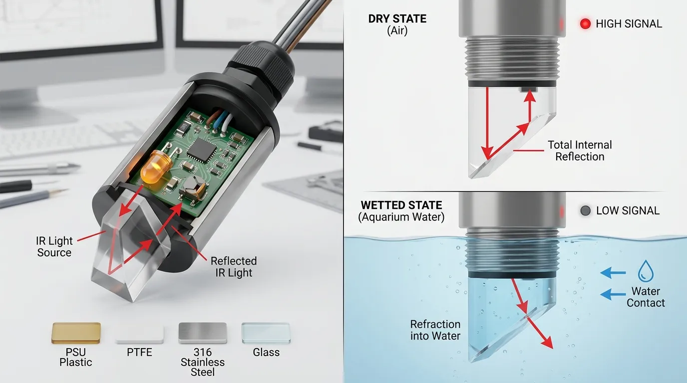
A reef ATO optical sensor works differently from a float switch. Inside the sensor body, an infrared LED sends light toward a small prism tip. A phototransistor receives reflected light. When the prism is dry, more light reflects internally. When the prism is wetted, the optical behavior changes, and the electronics report a different state.
This is why optical sensors have no moving float arm, but they still need a clean sensing surface. Salt creep, bacterial film, calcium deposits, and air bubbles can all affect the transition between dry and wet states.
For broader sensor selection, HojellyTek’s optical level sensor range covers photoelectric point-level designs for water, oil, coolant, and equipment-level detection. In aquarium systems, the important detail is not only the sensing principle but also the body material, seal design, cable exit, and controller compatibility.
Step 4: Wire the Sensor to the Apex / FMM
Plug the OS-1 or OS-1-M into the correct Apex/FMM input. Then open Apex Fusion and confirm that the port is recognized as the correct sensor type. Before connecting the ATO pump logic, manually test the sensor:
- Hold the sensor tip in air and note the state.
- Submerge the sensor tip in sump water and note the state.
- Move it slowly through the target water line.
- Confirm the state changes consistently.
- Label the input clearly, such as ATO_LOW or SUMP_LOW.
Do not assume OPEN and CLOSED until you test the actual sensor in your setup. In many Apex ATO examples, a dry lower optical sensor is treated as the “low water” condition, while a submerged sensor is treated as normal. Your programming should match the real state shown in Fusion.
Step 5: Configure ATO Control with Delay and Safety Limits
A good ATO configuration should not turn the pump on every time a ripple touches the optical tip. Add a delay so the sensor must remain in the low-water state for a short period before the pump runs. This reduces false starts from waves, pump vibration, or momentary bubbles.
Also add a maximum run-time protection. If the ATO pump runs too long, Apex should shut it off and alert you instead of continuing to add freshwater. This protects against a stuck state, empty reservoir, clogged tube, displaced sensor, or siphon issue.
A practical control logic should include:
- A normal low-water sensor condition to turn the ATO pump on.
- A wet/normal condition to turn the ATO pump off.
- A delay before activation.
- A maximum pump run-time.
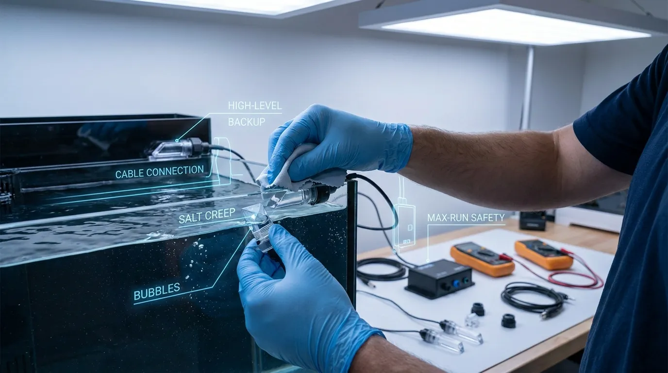
- A high-level backup sensor that forces the pump off.
- Optional reservoir-low protection to stop the pump before it runs dry.
Common Faults After Installation
| Problem | Likely Cause | Fix |
|---|---|---|
| Sensor triggers too often | Mounted in turbulent water | Move it to a calmer return chamber wall |
| Sensor remains in one state | Wrong port setup or loose plug | Reseat cable and confirm Fusion input type |
| ATO overfills | Sensor moved, dirty prism, or no safety timer | Clean sensor, secure mount, add max-run logic |
| Pump starts and stops rapidly | Waves or bubbles hitting the tip | Add delay and reposition sensor |
| Sensor works after cleaning, then fails again | Salt creep or biofilm buildup | Add routine cleaning schedule |
| Sensor reads incorrectly near glass/acrylic | Tip too close to wall or obstruction | Leave open water around the prism |
| ATO pump runs but level does not rise | Empty reservoir, clogged tube, or pump issue | Add reservoir sensor and pump timeout alarm |
Cleaning the Optical Sensor Tip
Turn off the ATO pump before cleaning. Remove the sensor or lower the water level enough to access the prism. Wipe the optical tip with a soft cloth and freshwater. If there is hardened salt or mineral film, soak the tip area briefly and clean gently. Avoid sharp tools, sandpaper, or aggressive scraping because scratches can affect optical performance.
A reef sump is harsh on sensors because salt spray dries into crystals, and organic film builds up over time. A simple cleaning routine is often the difference between reliable ATO control and random false triggers.
Add a Redundant Sensor for Safer ATO Operation
One optical sensor can control the normal fill level, but a redundant high-level sensor is strongly recommended. Mount the backup sensor slightly above the normal water line. Its job is not to control everyday top-off; its job is to stop the ATO pump if the lower sensor, mount, outlet logic, or pump control fails.
For higher-risk setups, use three protection layers:
| Protection Layer | Function |
|---|---|
| Primary optical sensor | Starts and stops normal ATO operation |
| High-level optical sensor | Stops ATO if water rises too high |
| Timer / max-run rule | Stops ATO if filling takes too long |
This layered approach is more reliable than depending on one sensor state alone.
Material and Output Notes for Compatible Optical Sensors
Neptune OS-1/OS-1-M sensors are designed for the Apex ecosystem. If you are sourcing a compatible or OEM aquarium sensor for your own controller, ATO product, or private-label aquarium device, the buying checks are different.
Confirm the wetted material first. Common optical sensor body materials include PSU plastic for compact water-level sensors, PTFE for chemical resistance, 316 stainless steel for rugged liquid applications, and glass for special chemical or temperature environments. For reef ATO use, the sensor must tolerate saltwater exposure, cleaning, and long-term immersion or splash contact.
Also confirm the electrical output. Industrial and OEM optical sensors may use NPN, PNP, relay-style switching, or analog 4–20 mA output depending on the control board. Aquarium ATO projects usually need a simple digital wet/dry signal matched to the controller input. Thread style, cable length, connector, seal, and mounting method should be confirmed before ordering.
If your goal is not Apex replacement but custom aquarium equipment, HojellyTek manufactures photoelectric liquid-level sensors in Shenzhen with in-house R&D, OEM/ODM customization, and export experience for US, EU, and India customers. For more details, see our aquarium optical sensor page or the aquarium auto top-off option.
OS-1 / OS-1-M vs Compatible Aquarium Optical Sensor
| Item | Neptune OS-1 / OS-1-M | Compatible Aquarium Sensor Direction |
|---|---|---|
| Best use | Apex / FMM-based reef ATO setup | OEM aquarium controller, ATO device, or replacement project |
| Mounting | OS-1 holder or OS-1-M magnetic mount | Threaded, bracket, magnetic, or custom housing |
| Output | Designed for Neptune ecosystem | Confirm NPN, PNP, digital, analog, or board-level signal |
| Customization | Limited to ecosystem accessories | Body material, cable, connector, output, mounting can be specified |
| Buyer focus | Easy Apex integration | Electrical and mechanical compatibility |
For buyers comparing options, our Neptune sensor alternative page explains how to think about compatibility without assuming Neptune endorsement.
FAQ
How to install neptune systems optical level sensor in a reef sump?
Mount the OS-1 or OS-1-M in the return chamber at the desired normal water line, secure the holder, plug the sensor into the Apex/FMM input, confirm the wet/dry state in Apex Fusion, then configure ATO pump logic with delay, max-run protection, and preferably a high-level backup sensor.
Should the Neptune optical sensor be underwater?
For ATO control, the tip sits at the target water line. During normal full level it may be wetted; when evaporation lowers the water below the tip, it becomes dry and triggers the refill logic. Always verify the actual state in Apex Fusion before programming.
Where should I mount the OS-1-M magnetic sensor?
Mount it on a stable wall of the return pump chamber, away from heavy bubbles, skimmer discharge, drain turbulence, and pump vibration. The prism tip should be clear of obstructions and aligned with the water height you want to maintain.
Why does my optical sensor give false triggers?
Common reasons include salt creep, dirty prism surface, bubbles, ripples, loose cable connection, wrong FMM port assignment, sensor movement, or poor placement near turbulent flow. Clean the tip, secure the mount, and add delay in the ATO logic.
How often should I clean an aquarium optical level sensor?
Clean it whenever you see salt film, algae, or inconsistent sensor readings. In reef sumps, a regular maintenance schedule is better than waiting for failure because dried salt and biofilm can affect the optical wet/dry transition.
Do I need a second optical sensor for ATO?
A second high-level sensor is strongly recommended. It acts as a backup shutoff if the primary sensor sticks, gets dirty, moves, or if the ATO logic behaves unexpectedly. Combine it with a maximum pump run-time for safer operation.
Compatible-Alternative Note
Neptune OS-1 and OS-1-M sensors are convenient for Apex users. For aquarium equipment brands, controller manufacturers, distributors, and OEM buyers who need a custom photoelectric water-level sensor, HojellyTek can support sensor body, mounting, cable, connector, and output matching at the RFQ stage. To discuss a compatible aquarium sensor or ATO project, request a quote via WhatsApp or email.