
Optical Infrared Water Level Sensor Documentation
This documentation for optical infrared water liquid level sensor modules puts the pinout, electrical limits, Ausgangslogik, Abmessungen, wiring notes, and troubleshooting points in one place for first-time users. Instead of treating the sensor like a loose parts-bin component, this guide explains how the IR optical sensing tip works, how to connect VCC/GND/OUT safely, and what to check before using the module in a tank, Gerät, or prototype.
HojellyTek manufactures photoelectric optical liquid level sensors in Shenzhen for OEM/ODM projects, Industrieausrüstung, smart appliances, Wassersysteme, and custom tank monitoring designs. Use this page as a practical starting point, then confirm the exact drawing, Ausgabetyp, and material before ordering.
Quick Pinout and Spec Table
Most common IR optical water/liquid level sensor modules use three basic connections: Macht, Spielfeld, and digital output. Some industrial versions may use NPN, PNP, analog, or current-loop outputs, so always match the sensor version to your controller input.
| Gegenstand | Common Label | What It Means | User Note |
|---|---|---|---|
| Positive power | VCC | Sensor supply input | Confirm the rated supply voltage before connecting power. Many small modules are designed for low-voltage control boards. |
| Spielfeld | GND | 0V reference | Must share ground with the microcontroller or control circuit. |
| Signal output | ENDE / VON | Digital wet/dry output | Connect to a controller input, Arduino digital pin, SPS-Eingang, or interface circuit according to the output type. |
| Ausgangslogik | HOCH / NIEDRIG | Changes when prism tip is dry or wetted | Logic may vary by module design, so test dry and wet states before installation. |
| Sensing method | IR optical prism | Infrarot-LED + receiver detects reflection change | No moving float is required. |
| Kalibrierung | Usually none for digital point-level use | Wet/dry switching is based on optical refraction | Perform a bench test; do not assume every liquid behaves the same. |
| Montage | Faden, Nuss, Dichtung, Flansch, or custom body | Fixes the sensor at one point level | Confirm tank wall thickness, Faden, Dichtungsverfahren, and probe orientation. |
| Dimensionen | Karosserielänge, Gewindegröße, sensing tip length, cable/wire length | Determines whether it fits the tank or panel | Use the model drawing before drilling, molding, or machining. |
| Benetztes Material | Netzteil, PTFE, 316 Edelstahl, Glas, or custom body | Material that contacts the liquid | Choose based on water, Öl, Chemikalien, Temperatur, Druck, and cleaning process. |
Für eine umfassendere Produktübersicht, see HojellyTek’s Optischer Pegelsensor Seite.
How the IR Optical Level Sensor Works
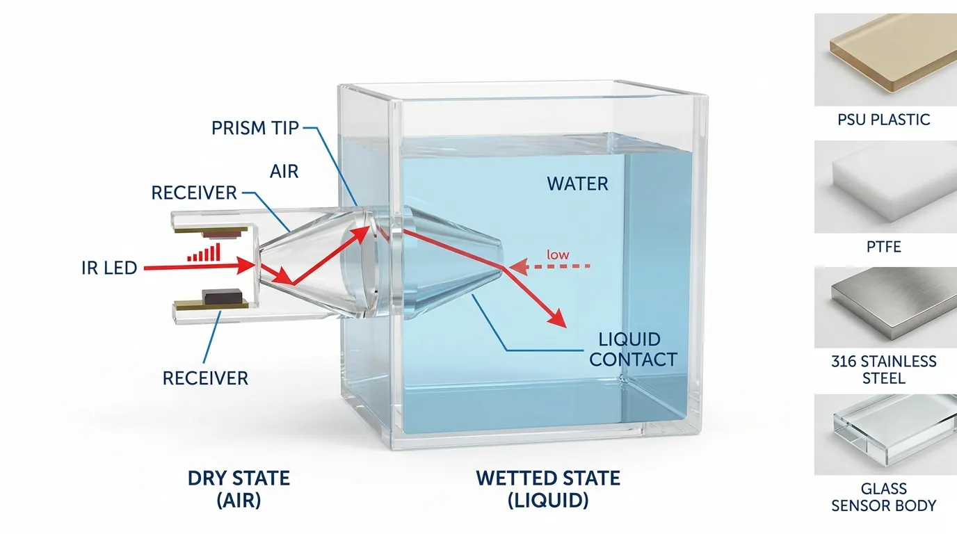
An optical infrared liquid level sensor uses an IR LED, einen Phototransistor- oder Photodiodenempfänger, und eine transparente Prismenspitze. When the prism is in air, infrared light reflects internally inside the tip and returns strongly to the receiver. Wenn Flüssigkeit das Prisma bedeckt, der brechungsbedingte Zustand ändert sich, daher kehrt weniger Licht zum Empfänger zurück. The circuit converts that change into an electrical output.
This is why optical level sensors are popular for compact water tanks, Kühlmittelreservoirs, condensate detection, dispensing systems, coffee machines, Luftbefeuchter, Medizinische Geräte, and small automation devices. There is no float arm, reed switch, Magnet, or mechanical hinge to jam. The sensor detects a fixed point level where the prism tip is installed.
Jedoch, the sensor is not a “magic water detector.” It must be matched to the liquid, Panzer, Verdrahtung, Montageposition, and controller input. Very reflective surfaces, Schaum, Blasen, Beschichtung auf dem Prisma, heavy contamination, and incorrect wiring can all cause confusing behavior.
Pinout: VCC, GND and OUT
For first-time users, the most important detail is simple: do not connect the sensor until you know which conductor is VCC, which is GND, and which is OUT.
VCC powers the internal IR emitter and signal circuit. The supply voltage must match the sensor version. If the module is designed for a low-voltage microcontroller board, do not connect it directly to a higher industrial voltage input unless the datasheet confirms that range.
GND is the reference point for the circuit. When used with Arduino, ESP32, STM32, or another controller board, the sensor ground and controller ground normally need to be common.
ENDE is the signal. On a simple module, it may behave like a digital HIGH/LOW output. On industrial versions, it may be NPN, PNP, open collector, Push-Pull, Staffel, or analog depending on the design. A PLC input and an Arduino input are not always wired the same way.
For step-by-step connection examples, use the dedicated Schaltplan Leitfaden.
Ausgangs-Logik: Dry vs Wet State
The output changes when the sensing prism is dry or covered by liquid. Some modules output HIGH when liquid is detected and LOW when dry. Other interface boards may invert the logic. That is why the safest first step is a simple bench test:
- Power the sensor with the correct supply.
- Read the OUT signal in air.
- Dip only the prism tip into water.
- Record whether OUT changes HIGH to LOW or LOW to HIGH.
- Use that logic in your controller code or PLC ladder program.
Do not design your final alarm logic before confirming this behavior. Zum Beispiel, a water tank “low-level alarm” and an “overflow alarm” may use the same sensor hardware but opposite logic in the control program.
Electrical Limits and Controller Compatibility
The main electrical checks are supply voltage, Ausgabetyp, Laststrom, pull-up or pull-down requirement, input voltage compatibility, and protection against reverse polarity or wiring mistakes. If any of these are unclear, do not guess.
For Arduino-style projects, a 5V module can often be connected to a digital input after confirming the signal level and wiring. For PLC or industrial control panels, the sensor output must match the input type. A PNP sensor typically sources current to the input, while an NPN sensor typically sinks current. If the controller expects one type and the sensor provides the other, the input may never switch correctly.
For small projects, Siehe die 5V-IR-Wassersensor Ressource. For microcontroller examples, refer to the Arduino guide.
Dimensionen, Mounting and Installation Position
Dimensions matter because this is a point-level sensor. The sensor does not measure the full tank height. It detects whether liquid has reached the prism tip.
Before ordering or drilling the tank, Bestätigen:
- Body diameter and body length
- Thread type or mounting style
- Nut, Dichtung, or sealing structure
- Probe tip position after installation
- Tank wall thickness
- Cable direction and bend space
- Whether the sensor is installed from the side, Nach oben, or bottom
- Whether the sensing point aligns with the real alarm or control level
A common beginner mistake is mounting the sensor where splashing, waves, or bubbles touch the prism before the actual liquid level reaches the control point. In diesem Fall, software filtering may help, but better mechanical placement is usually more reliable.
For custom equipment, HojellyTek can support threaded, flange-mounted, kompakt, and material-specific sensor structures based on the tank design.
Wetted Material Choices
The material touching the liquid is not just a cosmetic choice. It affects chemical compatibility, temperature resistance, hygiene, pressure suitability, und langfristige Zuverlässigkeit.
Netzteil oder Ingenieurkunststoff is common for compact water and appliance-level sensing where cost, Größe, and easy molding matter.
PTFE is preferred for many chemical liquids because of its strong corrosion resistance and low surface adhesion.
316 Edelstahl is used where rugged construction, Mechanische Festigkeit, and industrial appearance are important.
Glass optical tips can be useful for certain laboratory, Hochtemperatur, or chemically demanding applications, depending on the full structure and sealing method.
Das beste Material hängt von der Flüssigkeit ab, Reinigungsprozess, working temperature, Druck, Winkelinstallation, and whether the sensor must meet an OEM housing requirement.
Does the Sensor Need Calibration?
For a normal digital optical point-level sensor, calibration is usually not required in the way an analog level transmitter needs calibration. The sensor detects a wet/dry state at the prism tip.
But “no calibration” does not mean “no testing.” Always test the sensor with the real liquid when possible. Wasser, Öl, Kühlmittel, Schaum, Reinigungsmittelmittel, and chemical liquids can behave differently around the prism. If the liquid leaves residue on the optical tip, the sensor may need cleaning intervals or a different material.
For production equipment, define the test condition clearly: Trockener Zustand, wetted state, response time expectation, installation orientation, and acceptable controller logic.
Fehlerbehebung bei häufigen Problemen
The output never changes
Check VCC and GND first. Then confirm the supply voltage, wire order, and whether OUT is connected to the correct input type. If the sensor has an open-collector output, the circuit may need a pull-up or pull-down path.
The sensor is always HIGH or always LOW
Do a dry/wet bench test outside the tank. If the logic changes during the bench test but not in the tank, the problem is likely installation position, Schaum, Blasen, Beschichtung, or liquid behavior. If it never changes during the bench test, wiring or output compatibility is more likely.
Readings are unstable
Look for turbulence, Platschen, Schwingung, weak power supply, long unshielded cable runs, or poor grounding. In software, add a short delay or require the signal to stay stable before switching a pump or alarm.
The sensor works in water but not in another liquid
Optical sensors depend on light behavior at the prism. Liquids with different refractive properties, Farbe, Blasen, Kontamination, or residue can affect detection. Test with the actual liquid before mass production.
The sensor failed after installation
Check overvoltage, Umgekehrte Polarität, liquid leakage through the mounting seal, Chemischer Angriff, Kabeldehnung, und Reinigungschemikalien. Many field failures are not sensing failures; they are wiring, Versiegelung, or material-selection problems.
Before You Order or Build Around the Sensor
Prepare these details before sending an RFQ or choosing a module:
- Flüssiger Typ: Wasser, Öl, Kühlmittel, Chemikalie, Abwasser, oder gemischte Flüssigkeit
- Erforderliche Ausgabe: Digital, NPN, PNP, analog, 4–20 mA, oder benutzerdefinierte Schnittstelle
- Control board: Arduino, SPS, Haushaltsleiterplatte, IoT module, or industrial gateway
- Supply voltage and input voltage limits
- Wet/dry output logic required by the system
- Montagegewinde, Flansch, Nuss, Dichtung, or custom body
- Wetted material requirement
- Tank wall thickness and sensing point position
- Kabellänge, Steckverbinder, and wire color preference
- Betriebsumgebung: Hallenbereich, Im Freien, Schwingung, Wärme, Kondensation, or cleaning exposure
For smart appliance or IoT projects, our team can also discuss integration with control boards, OEM cable assemblies, and Tuya/Smart Life-related product requirements where relevant.
When to Use a Module vs an Industrial Optical Sensor
A small IR optical water level module is useful for learning, prototyping, Arduino testing, and compact low-voltage equipment. It is simple, fast to test, and easy to understand.
An industrial or OEM optical liquid level sensor is better when the project needs defined material, sealed housing, stable cable, specific output logic, repeatable production testing, custom dimensions, or export-ready supply. HojellyTek supports in-house R&D, photoelectric optical sensing design, OEM/ODM-Anpassung, and export projects for customers in the US, WIR, Indien, und andere Märkte.
Häufig gestellte Fragen
What is included in this documentation for optical infrared water liquid level sensor users?
It covers the practical details users usually need first: VCC/GND/OUT pinout, electrical limits to confirm, wet/dry output logic, Abmessungen, mounting notes, calibration expectations, wiring cautions, and troubleshooting.
Is the output HIGH or LOW when the sensor touches water?
It depends on the module circuit. Some sensors output HIGH when wet; others may output LOW or use inverted logic. Always test the sensor in dry and wet states before writing final control logic.
Can I connect an optical water level sensor directly to Arduino?
Many low-voltage modules can be used with Arduino after confirming the supply voltage, signal voltage, and output type. If the output is NPN, PNP, open collector, or industrial voltage, use the correct interface circuit.
Does an optical infrared water level sensor need calibration?
A digital point-level optical sensor usually does not need calibration. It should still be tested with the real liquid, tank position, and controller input before final installation.
Why does my optical sensor stay triggered after the liquid is removed?
Residue, droplets, Schaum, Ölfilm, or contamination on the prism can keep the optical path changed. Reinige die Spitze, test with the real liquid, and consider a different wetted material if residue is frequent.
What should I send HojellyTek for a custom sensor quote?
Senden Sie den flüssigen Typ, Versorgungsspannung, Ausgabetyp, Nass-/Trockenlogik, Montagemethode, material requirement, Abmessungen, Kabellänge, Steckverbinder, quantity target, and application photos or drawings. You can request a quote by WhatsApp or email.