
Optúil (Infridhearg) Water Level Sensor Wiring Diagram
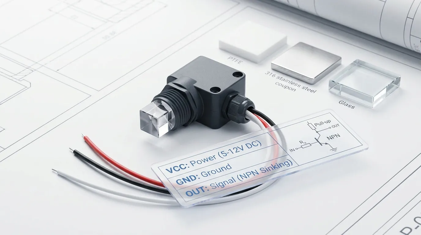
An optical level sensor wiring diagram for a typical 3-wire optical/IR water level sensor is simple: connect VCC to a 5V supply, GND to the common ground, is OUT to the digital input, relay module input, or control-switch signal terminal. For an Aschur bailitheoir oscailte NPN, the OUT wire does not always generate a voltage by itself; it usually needs a pull-up so the controller can read a clear HIGH/LOW signal.
In practical terms: power the sensor, share the ground, pull the signal up, then let the OUT wire switch the controller input or relay interface. Do not start by guessing wire colors—confirm the pinout from the datasheet or supplier documentation before applying power.
Quick Wiring Diagram in Words
For a common 3-wire optical water level sensor:
VCC → 5V DC
Connect the sensor’s positive supply wire to the controller’s 5V output or a regulated 5V power supply.
GND → 0V / Talamh
Connect the sensor ground to the power supply ground and the controller ground. ArduinoCity name (optional, probably does not need a translation, Raspberry Pi interface boards, PLC inputs, relay modules, and sensor power must share a reference ground.
OUT → Digital input or relay control input
Connect OUT to the input pin that needs to detect liquid presence. If the sensor is NPN open-collector, OUT works like a sinking switch. It pulls the signal down when active, so the input normally needs a pull-up to 5V.
Pull-up → OUT to VCC
The pull-up makes the signal readable when the NPN transistor is not pulling it low. Some microcontrollers can use an internal pull-up; industrial controllers or relay modules may require the correct input wiring according to their circuit design.
Relay or control switch → use an interface
If you are switching a pump, comhla, Aláram, or relay, use a relay module or transistor/driver circuit. Do not assume the sensor OUT wire can power a relay coil directly.
For deeper board-level examples, féach an Arduino guide is Raspberry Pi guide.
3-Wire Optical / IR Water Level Sensor Pinout Table
Wire colors are common examples only. Always confirm the actual pinout before wiring, especially for OEM/ODM sensors, panel-mount versions, agus tionóil cábla saincheaptha.
| Sensor Pin / Wire | Feidhm tipiciúil | Connect To | Wiring Notes |
|---|---|---|---|
| VCC / +V | Sensor power input | 5V DC supply in a typical test setup | Use the voltage specified for your sensor model. For this guide, the basic wiring example uses 5V. |
| GND / 0V | Power return | Controller ground and power supply negative | The ground must be shared between the sensor and the device reading the signal. |
| AMACH / Comhartha | Switching output | Ionchur digiteach, relay module input, control switch input, PLC input interface | For NPN open-collector output, use a pull-up so the input can read HIGH when the output is not sinking. |
| Pull-up connection | Signal reference | OUT to VCC | Needed when the input does not already provide a pull-up. |
| Relay/control interface | Load control | Modúl sealaíochta, transistor driver, nó ionchur an rialaitheora | Use an interface stage for pumps, comhla, aláraim, or higher-current loads. |
How the NPN Open-Collector Output Works
Many 3-wire optical/IR water level sensors use an NPN open-collector Aschur. This means the sensor output behaves like a switch to ground, not like a powered voltage output.
When the sensor output is inactive, the OUT wire may float unless a pull-up is present. With a pull-up, the input reads HIGH. When the sensor output becomes active, the internal transistor pulls OUT toward ground, so the input reads LOW.
This is why many users think the sensor is “not giving voltage.” In reality, the output may be working correctly, but the circuit is missing a pull-up or the controller input is not configured correctly.
For a microcontroller, OUT usually connects to a digital input. For an industrial controller, OUT may connect to a compatible digital input channel. For a relay module, OUT should connect to the signal input only when the module input type is compatible with a sinking NPN signal.
Wet vs Dry Logic: NO and NC Behavior
Optical water level sensors detect whether the sensing tip is in air or covered by liquid. Taobh istigh den braiteoir, an IR LED sends light into a prism tip, and a phototransistor detects the returned light. When the tip is dry, light reflects differently inside the prism. When liquid covers the tip, Athraíonn an coinníoll athraonta, so the receiver sees a different signal.
The output logic depends on the sensor design:
- NO logic may switch ON only when liquid reaches the sensing tip.
- NC logic may switch OFF when liquid reaches the sensing tip.
- Some products are available in different output versions.
- Some control systems invert the logic in software instead of changing hardware.
Because wet/dry behavior can vary by model, do not rely only on the label “optical water level sensor.” Confirm whether your required safe state is wet = active, dry = active, wet = LOW, nó dry = LOW.
For pump dry-run protection, many engineers prefer a logic arrangement where a broken wire or lost signal can be treated as a fault. For overflow alarms, the priority is often fast detection when the liquid reaches the high-level point.
Connecting to a Relay or Control Switch
If the optical sensor is used as a control switch, the OUT signal should normally drive a control input, not the load directly.
A safe wiring concept is:
Sensor VCC → 5V
Sensor GND → common ground
Sensor OUT → relay module input or controller input
Relay contacts → pump, comhla, buzzer, Aláram, or control circuit
The relay contacts do the load switching. The sensor only provides the level signal.
For a bare relay coil, use a proper driver stage. The sensor output is not intended to replace a relay driver unless the current rating and circuit design are confirmed. Inductive loads also need protection such as suppression across the coil or load circuit. In OEM equipment, this is usually handled on the control PCB or relay module.
If you are building a simple prototype, a relay module with a signal input is easier than a loose relay coil. If you are designing a product, confirm the input type, trigger polarity, load current, isolation needs, and fault behavior before finalizing the wiring.
Testing the Sensor Before Installation
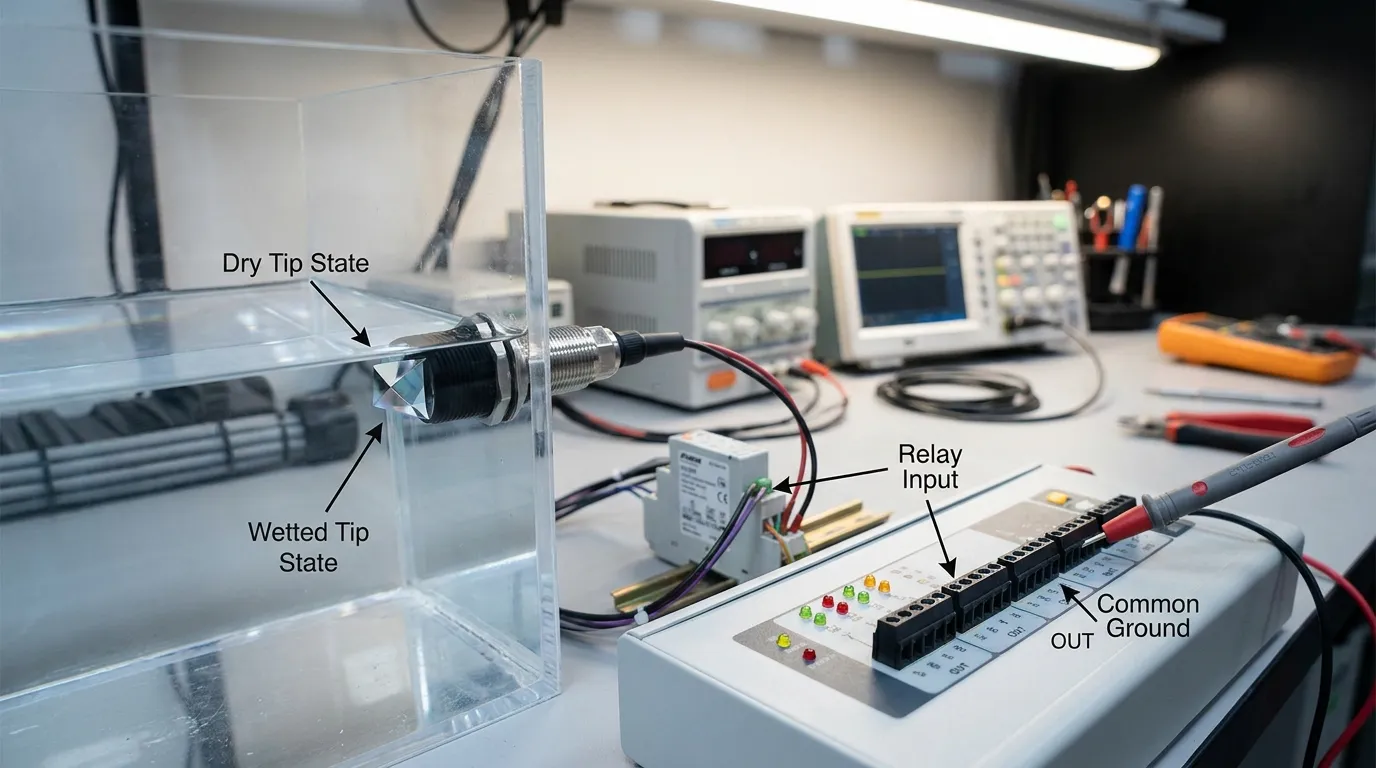
Test the wiring on the bench before installing the sensor in a tank.
An Chéad, connect VCC and GND to the correct 5V supply and verify polarity. Then connect OUT to a digital input or meter test point with the correct pull-up. Keep the sensing tip dry and observe the output state. Ar aghaidh, cover the prism tip with water and observe whether OUT changes.
If the signal changes when the tip is wetted, the sensor is switching. If the signal does not change, check the power, talamh, pull-up, and logic mode before blaming the sensor.
A multimeter can help, but remember that an open-collector output may not show a clean voltage unless the pull-up and common ground are correct. For microcontroller testing, print the input state in software. For relay testing, watch the relay module indicator and listen for the relay action only after confirming the module is wired correctly.
For more technical product notes, féach an Doiciméadú braiteoir IR.
Common Wiring Faults and Fixes
No shared ground
The sensor has power, but the controller cannot read OUT correctly. Connect sensor GND and controller GND together.
No pull-up on NPN OUT
The output floats and gives unstable readings. Add or enable a pull-up according to the controller input design.
Wrong wire color assumption
Not every supplier uses the same cable colors. Deimhnigh VCC, GND, and OUT before applying power.
Reversed wet/dry logic
The sensor works, but the software or relay action is opposite. Confirm NO/NC logic and invert the input in software or select the correct output version.
Trying to drive a relay coil directly
The output may fail or the relay may not switch. Use a relay module, transistor driver, or controller input stage.
Dirty prism tip
Oil film, scála, foam residue, or adhesive contamination can prevent reliable optical switching. Clean the prism and check chemical compatibility.
Reflective or tight mounting area
Tank wall reflections, boilgeoga, or poor positioning may cause unstable detection. Mount the sensor so the prism tip contacts the target liquid cleanly.
Wrong sensor material
Uisce, ola, ceimiceáin, food-grade fluids, breoslaí, and corrosive liquids require different wetted materials. Confirm compatibility before ordering.
Ábhair, Gléasta, and Output Options Buyers Should Check
A wiring diagram solves the electrical connection, but the right sensor selection depends on the liquid, Dearadh umar, and controller.
For optical/photoelectric point-level detection, the sensing tip is often made from a transparent prism material. Depending on the application, buyers may need PSU, PTFE, 316 tithíocht cruach dhosmálta, or glass-contact designs. Water tanks and appliances may use compact plastic-bodied sensors. Chemical tanks may require PTFE or stainless construction. Oil and fuel applications need careful material review because swelling, Staining, or residue can affect long-term reliability.
Mounting also matters. Some sensors are installed through a threaded port, while others use panel mounting, custom flanges, compact probe shapes, or cable-mounted assemblies. The prism tip must sit at the real switching height, not above a dead zone or inside a pocket where liquid does not reach cleanly.
Output type is another purchasing decision. NPN is common for sinking digital inputs. PNP may be preferred by some industrial control systems. For continuous level measurement, buyers may consider analog output such as 4–20 mA instead of a simple point switch. This article focuses on the 3-wire point-level wiring because that is the most common need behind the wiring diagram search.
HojellyTek manufactures photoelectric optical sensing products in Shenzhen with in-house R&D, Tacaíocht OEM / ODM, and export experience for the US, TÁIMID, agus an India. For the broader sensor category, visit the Braiteoir Leibhéal Optúil Leathanach.
Cad atá le deimhniú sula n-ordaíonn tú
Before buying a 3-wire optical/IR water level sensor, Deimhnigh:
- Supply voltage required by your control board
- Cineál aschuir: NPN, PNP, analógach, nó comhartha saincheaptha
- Wet/dry logic: NO or NC behavior
- Pull-up or input circuit requirement
- Liquid type and wetted-material compatibility
- Snáithe gléasta, panel hole, Flange, or custom installation method
- Fad cábla, cónascaire, and wire color definition
- Whether the sensor will drive a controller input, Modúl sealaíochta, rialú caidéil, Aláram, or IoT board
- Required housing material for water, ola, breosla, ceimiceach, or appliance use
- Whether OEM labeling, cable customization, or module integration is needed
For smart home or connected equipment, Tuya/Smart Life integration may be relevant at the system level, but the sensor wiring itself still begins with the same basic rule: cumhacht, talamh, comhartha, and correct input logic.
Ceisteanna CCanna
What is the basic optical level sensor wiring diagram?
The basic wiring is VCC to 5V, GND to common ground, and OUT to the input pin or relay module signal input. For an NPN open-collector output, add or enable a pull-up so the signal can switch cleanly between HIGH and LOW.
Does a 3-wire optical water level sensor need a pull-up resistor?
If the output is NPN open-collector, Tá, the signal usually needs a pull-up. Gan é, OUT may float and the controller may read unstable or incorrect states. Some boards provide internal pull-ups, but this must be confirmed in the input circuit.
Can I connect the sensor directly to a relay?
Connect the sensor to a relay module input or driver circuit, not directly to a high-current relay coil unless the sensor rating and circuit design confirm it is safe. For pumps, comhla, agus aláraim, use the relay contacts to switch the load.
Why does the output stay HIGH or LOW all the time?
Common causes include missing common ground, no pull-up, reversed supply polarity, wrong input logic, incorrect NO/NC assumption, dirty prism tip, or using the wrong output type for the controller. Test the sensor dry and wet before installing it.
Is wet detection normally open or normally closed?
Braitheann sé ar an tsamhail. Some sensors activate when liquid covers the tip; others deactivate. Confirm wet/dry logic before ordering, especially for overflow protection, cosaint tirim-rith, and alarm circuits where fail-safe behavior matters.
Can I use the same sensor with Arduino and Raspberry Pi?
Tá, but the wiring details differ because the input voltage and pull-up arrangement may differ by board. Use the dedicated Arduino and Raspberry Pi wiring guides before connecting the sensor to a development board.
Need Help Matching the Wiring to Your Control Board?
Share your supply voltage, Cineál an rialaitheora, Riachtanas aschuir, leachtach, Modh gléasta, and wet/dry logic preference with HojellyTek. Our team can help you confirm the correct 3-wire optical/IR water level sensor wiring, NPN or PNP output choice, material option, and OEM/ODM configuration. Request a quote via WhatsApp or email for samples, datasheets, or custom sensor support.