
Optical Level Sensor Specifications & Selection
This optical level sensor specification resource helps buyers compare the key electrical, mechanical, and wetted-material details before requesting a datasheet, sample, or quote. HojellyTek manufactures photoelectric optical level sensing solutions in Shenzhen for OEM/ODM projects, industrial tanks, appliance reservoirs, oil systems, water systems, and exported sensor assemblies for US, EU, and India buyers.
Use this page as a selection checklist before choosing an optical level sensor for your tank, controller, or equipment design.
Optical Level Sensor Specification Sheet
An optical level sensor is normally selected by matching the control system first, then the tank and liquid environment. The buyer should confirm power supply, current load, output type, switching logic, wetted materials, temperature, pressure, mounting thread, cable style, and IP protection before ordering.
| Specification Item | HojellyTek Standard Range / Status | Buyer Selection Note |
|---|---|---|
| Sensing principle | Photoelectric optical sensing | IR LED + phototransistor + prism tip |
| Supply voltage | 5–24VDC | Match PCB, PLC, relay module, or controller input |
| Supply current / current consumption | TBC | Confirm during RFQ based on model and circuit design |
| Load current | ≤100mA | Check controller input/load limit before wiring |
| Output type | NPN / PNP | Choose according to PLC/controller input type |
| Output function | NO / NC | Select based on high-level alarm, low-level alarm, or fail-safe logic |
| Switching response | TBC | Confirm if the liquid level changes quickly or the tank has vibration |
| Standard housing material | SUS316 | Suitable for many water, oil, and industrial liquid-contact applications |
| Standard sensing tip / prism material | Glass | Used for optical reflection change between dry and wetted states |
| Other material choices | PSU / PTFE / 316 stainless / glass, confirm by project | Use RFQ review for chemical, temperature, and OEM housing requirements |
| Operating temperature | -10~80℃ | Confirm liquid temperature, ambient temperature, and cleaning cycle |
| Pressure rating | TBC | Confirm for sealed tanks, pressure vessels, pumps, or fuel systems |
| Thread / mount options | 1/2” NPT, G1/2, 3/8” NPT | Match tank boss, wall thickness, gasket, and installation direction |
| IP rating | IP67 | Suitable for protected industrial and equipment installations |
| Indicator light | Red: power; Green: water status | Useful for bench testing and field troubleshooting |
| Datasheet / drawing / wiring | Available by request | Use a form, WhatsApp, or email to request the correct model file |
How the Optical Sensing Specification Works
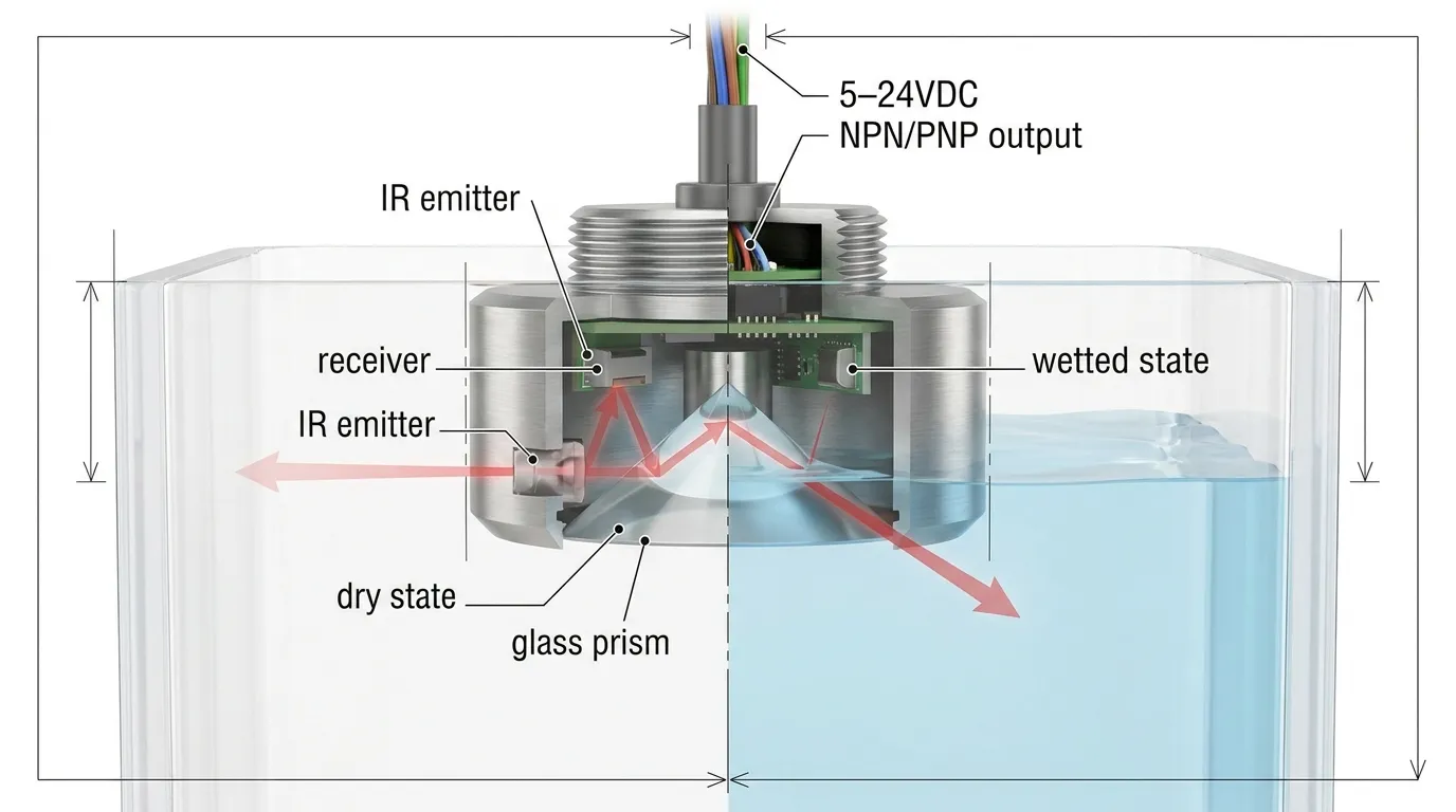
A photoelectric optical level sensor uses an infrared LED, a phototransistor receiver, and a prism-shaped sensing tip. In the dry state, the prism reflects light internally back to the receiver. When liquid covers the prism, the optical path changes because the liquid has a different refractive behavior from air. The electronics convert that optical change into a switching output.
This makes optical point level sensors useful where the buyer wants compact size, no moving float, fast electronic switching, and a clean signal for low-level or high-level detection. However, the specification must fit the real liquid and installation. Foam, bubbles, heavy coating, strong contamination, poor mounting angle, incorrect output wiring, or incompatible wetted materials can all create field problems.
Match Electrical Specs to the Controller
The first selection step is power and output. HojellyTek’s standard supply voltage range is 5–24VDC, which allows use in many low-voltage control boards, appliance systems, industrial controllers, and OEM tank monitoring circuits.
For simple point-level detection, the standard output choices are NPN or PNP. NPN is commonly selected where the input expects a sinking signal, while PNP is used where the input expects a sourcing signal. The wrong output type may make the sensor appear “dead” even when the sensing tip is working correctly. For wiring details, compare the NPN/PNP output guide before confirming the order.
Some projects ask about 4–20 mA because they are used to continuous level transmitters. For this resource page, the confirmed standard range is for optical point level switching. If the application requires an analog continuous signal, the output requirement should be reviewed separately at the RFQ stage rather than assumed.
Load current is also important. The confirmed standard load current is ≤100mA. If the sensor drives a PLC input, this is usually a signal-level load. If the buyer wants to drive a relay, lamp, buzzer, or solenoid directly, the circuit must be reviewed carefully because those loads may exceed the sensor output rating.
Select NO or NC Logic for the Alarm Function
The same sensor body may be used for different control purposes depending on the switching logic. NO and NC should be selected according to how the machine should behave when the sensing point is dry, wet, disconnected, or in alarm.
For a low-level protection tank, the buyer may want the controller to stop a pump when liquid drops below the sensor. For an overflow alarm, the buyer may want a signal when liquid reaches the upper point. In safety-related designs, the control engineer should decide whether the normal state should be energized or de-energized so that cable failure, sensor failure, or power loss does not create an unsafe assumption.
Wetted Materials and Liquid Compatibility
The wetted parts decide whether the sensor can survive the liquid. Buyers often compare PSU, PTFE, 316 stainless steel, and glass because each material behaves differently with water, oil, fuel, coolant, chemical liquids, cleaning agents, and temperature cycles.
For the current standard listed configuration, the confirmed housing material is SUS316 and the sensing tip is glass. This combination is useful where corrosion resistance, mechanical durability, and a stable optical prism surface are required. PTFE may be considered for more aggressive chemical environments, while PSU-style housings may be relevant for compact or cost-sensitive OEM applications, but material availability and suitability should be confirmed during RFQ.
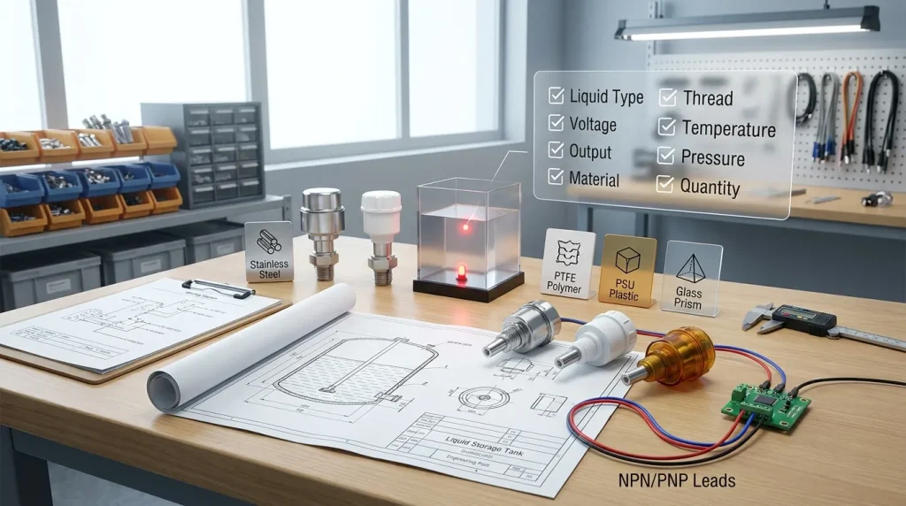
Before ordering, share the liquid name, concentration, temperature, whether the liquid leaves residue, whether the tank is cleaned with chemicals, and whether the sensor tip may be exposed to oil film, scale, foam, or suspended particles. Optical sensors work best when the prism surface can clearly transition between air and liquid.
Temperature, Pressure, IP Rating and Mounting
The confirmed operating temperature range is -10~80℃. This should be checked against both the liquid and the surrounding equipment temperature. A tank in a warm factory may still be within range, while a boiler-side, sterilization, or high-temperature cleaning environment may need a separate model review.
Pressure rating is marked TBC because it depends on the mechanical structure, seal, thread, and final model configuration. If the sensor will be used in a closed tank, pump line, fuel system, coolant circuit, or vessel with pressure fluctuation, pressure must be confirmed before sample approval.
The confirmed IP rating is IP67, which supports many equipment and industrial installations when the cable exit, connector, and installation method are protected properly. IP rating should not be treated as chemical compatibility or unlimited submersion permission; it is only one part of the environmental selection.
Mounting threads include 1/2” NPT, G1/2, and 3/8” NPT. Choose the thread according to tank boss design, wall thickness, gasket method, liquid direction, and available space for the cable. For OEM tanks, confirm whether the sensor installs horizontally from the side wall, vertically from the top, or into a custom chamber.
Application Mapping Table
| Application | Specs to Prioritize | Selection Notes |
|---|---|---|
| Water tank high/low alarm | 5–24VDC, NPN/PNP, NO/NC, IP67 | Confirm controller input type and alarm logic |
| Oil or fuel reservoir | SUS316, glass tip, thread seal, pressure TBC | Confirm oil film, vibration, and temperature |
| HVAC condensate or drain pan | Compact mounting, IP67, NO/NC | Check contamination, cleaning, and cable routing |
| OEM appliance tank | Voltage, output, thread, body size | Confirm sample fit before mold or tank design is finalized |
| Industrial liquid tank | Material, temperature, pressure, mounting | Share liquid data and installation drawings |
| Pump dry-run protection | Switching logic, response TBC, load current ≤100mA | Confirm fail-safe behavior in controller program |
How to Specify an Optical Level Sensor
Use this checklist before requesting the optical level sensor datasheet or a factory quote.
- Confirm the liquid: water, oil, fuel, coolant, chemical mixture, wastewater, or another liquid.
- Confirm the function: high-level alarm, low-level alarm, dry-run protection, overflow prevention, or OEM status detection.
- Confirm electrical input: 5V, 12V, 24V, PLC input, MCU input, relay module, or control board.
- Choose output type: NPN or PNP.
- Choose switching logic: NO or NC.
- Confirm load current requirement and whether the sensor only sends a signal or drives another device.
- Confirm material needs: SUS316, glass, PTFE, PSU, or custom discussion.
- Confirm tank mounting: 1/2” NPT, G1/2, 3/8” NPT, side mount, top mount, or OEM structure.
- Confirm temperature and pressure conditions.
- Share drawing, quantity target, cable/connector preference, labeling needs, and export destination.
Common Failure Modes to Avoid
Most optical level sensor problems are not caused by the sensing principle itself. They usually come from mismatch between the specification and the application.
A wrong NPN/PNP choice can prevent the controller from reading the signal. A wrong NO/NC choice can reverse the alarm logic. A liquid that coats the prism can delay or block the optical transition. Air bubbles, foam, or turbulent liquid can create unstable switching near the sensing point. A thread mismatch can cause leakage. A pressure condition that was not disclosed can affect sealing. A load above ≤100mA can damage the output circuit.
The safest approach is to approve the specification, wiring, drawing, and sample test before batch production.
HojellyTek Manufacturing Support
HojellyTek is a Shenzhen manufacturer and exporter focused on photoelectric optical sensing, liquid level detection, and OEM/ODM sensor projects. Our in-house R&D team supports model selection, wiring confirmation, material review, and customization discussions for equipment manufacturers, distributors, and industrial buyers.
For broader model details, review the optical level sensor product page, then send your application requirements by WhatsApp or email for confirmation.
FAQ
What should an optical level sensor specification include?
An optical level sensor specification should include supply voltage, current, output type, load current, switching logic, response requirement, wetted materials, operating temperature, pressure condition, thread size, mounting direction, IP rating, cable/connector needs, and the target liquid.
Is 5–24VDC suitable for my controller?
It may be suitable if your control board, PLC, or input module works within that supply range. You still need to confirm NPN/PNP output, NO/NC logic, load current, and wiring method before ordering.
Can one sensor detect both water and oil?
Optical sensors can be used in different liquids, but the liquid’s optical behavior, coating tendency, viscosity, temperature, and chemical compatibility must be reviewed. Water, oil, and fuel projects should not be treated as identical without sample testing.
What is the difference between SUS316, PTFE, PSU and glass?
SUS316 is commonly selected for corrosion resistance and mechanical strength. Glass is used as the optical prism tip. PTFE may be considered for aggressive chemicals. PSU-style material may suit some OEM designs. Final material selection should match the liquid and installation.
Do optical level sensors measure continuous level?
Standard optical point level sensors detect whether liquid is present at a fixed sensing point. If your project requires continuous level measurement or 4–20 mA output, state that clearly during RFQ so the correct solution can be reviewed.
Why are pressure and switching response marked TBC?
They depend on the exact model, seal, mechanical structure, and project conditions. Instead of inventing figures, we confirm pressure rating and switching response during datasheet review, sample approval, or custom specification discussion.
Download Datasheet or Request a Quote
To receive the correct datasheet, drawing, wiring guide, and quotation, send your liquid type, voltage, output requirement, thread size, mounting direction, material preference, temperature, pressure condition, and estimated quantity.
Contact HojellyTek by WhatsApp or email to request a datasheet, sample discussion, or OEM/ODM quote for your optical level sensor project.